Build Log of the Dragon MIM-104B Patriot PAC-1
w/M983 HEMTT in 1/35 scale PART 1
By Richard Geraci
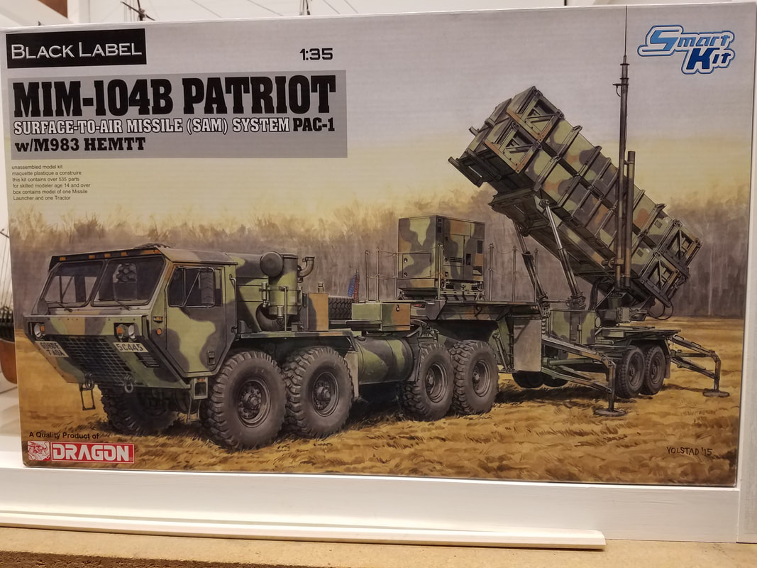
Ok, call me crazy but I'm starting the Dragon “Black Death” . . . er, “Black Label” Patriot PAC-1 w/HEMTT [1]. The Patriot system was (is) built down in Camden, at least partially now, so there is an Arkansas connection. They also build the M270-A1 MLRS, THAAD, and HIMARS down there, among other things. I'm hoping the kit does not live up to the Black Label reputation but we'll see. It's a big box with about 530 pieces on 13 light gray sprues, one clear sprue, a small decal sheet and Dragon DS tires (Boo-Hiss). Also a short length of braided stainless wire but no photoetch – rather unusual for a 2017 kit. The M983 HEMTT is actually the old Italeri M977 kit from maybe 20 years ago with a few part changes. If you are looking for accuracy in this kit, forget it. The kit sells for between $100 and $150 now. I gave $117 for it back in 2017. The instructions are typical Dragon – busy, incomprehensible, vague, mis-numbered in several places, and a bit out of sequence. Wait, this is supposed to be a “Smart Kit”. Guess that means you had better be pretty smart to figure out how to build it. A number of in-box reviews and sprue photos are available on the net so I won't waste space here duplicating them. Take a look out there if you are interested.
The first 15 steps are to build the trailer and launch system including four missiles (which do not appear to be able to fit into the weapon pods ??), with steps 16-30 being for the HEMTT. I'll probably display the missiles separately anyway. I usually build a kit in sub-assemblies to make painting easier so bear with me as I jump around some in the instructions. So, let's get started with the trailer.
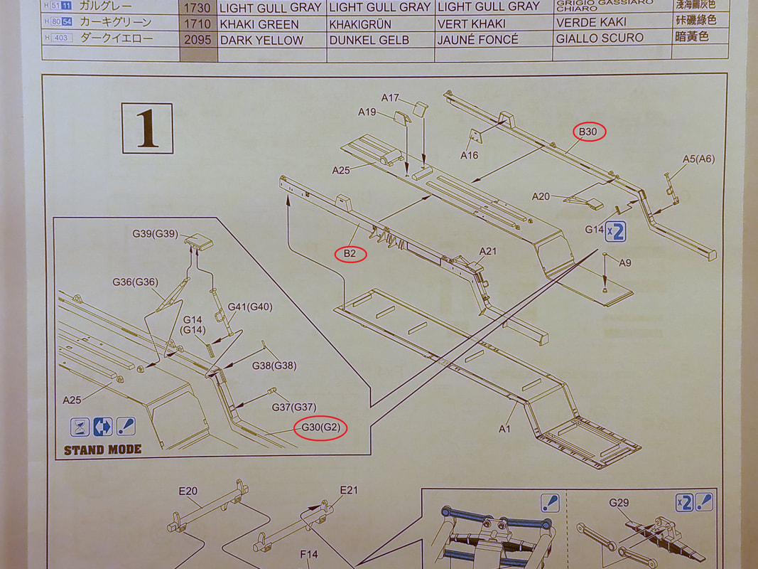
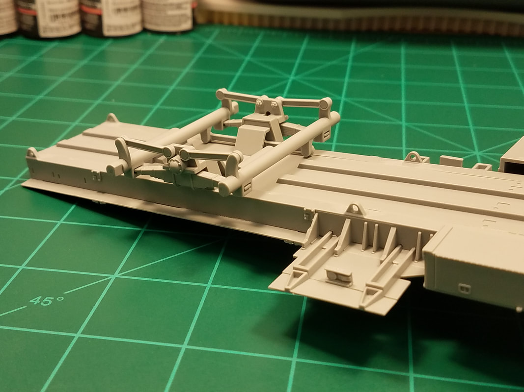
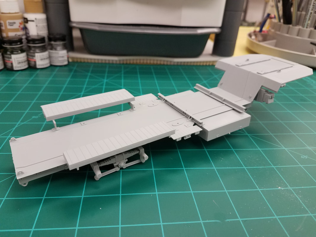
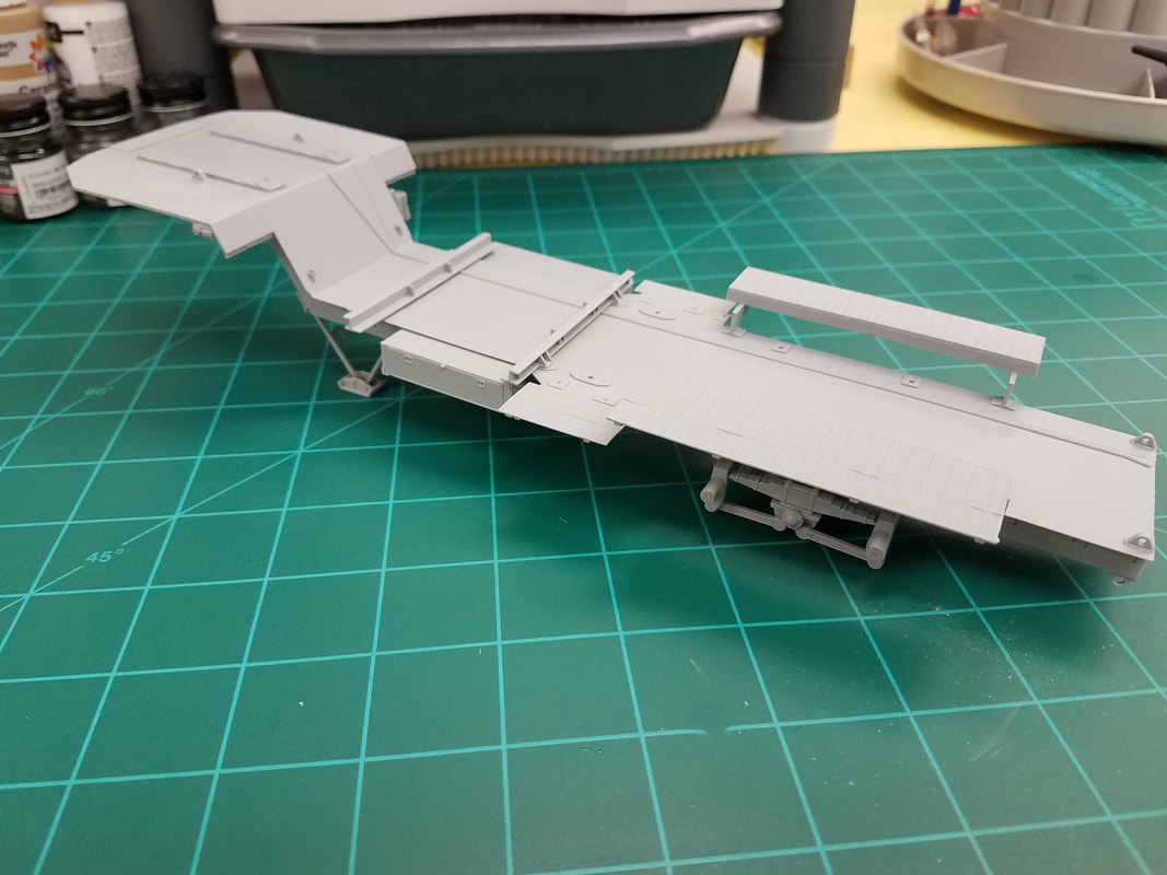
Right from the start [2] you have to decide whether you want to display the PAC-1 in the travel or launch position. While the pods can be made movable (supposedly), in Step 1 the trailer skids must be posed folded or extended. Your choice. Mine will be extended. I hope attaching them to the chassis now rather than later in the build doesn't get them broken. That said, there is a parts numbering snafu in this very first step. The chassis side rails are parts B30(B2) not G30(G2). This does not bode well for the rest of the build. Here is the trailer bed with the skids attached [3]. Step 2 [4] adds some suspension and storage parts to the chassis. And another numbering snafu – one part B36 should be B35. All these pieces went together without a problem though[5].
Beginning with Step 3 [6] things start to get interesting. Note you will need just over 192mm (measured straight, hole-to-hole) of the braided wire to make the top cable railing. They give you 240mm so that should be enough. But wait, you have TWO cable railings. Somebody forgot to include enough wire to do both. So you have a choice: omit the railings entirely or use something else for the cables. I will do the latter since I won't be installing the cables until after painting anyway. I have some braided silver thread that is about the right size and can replicate the sag better anyway.
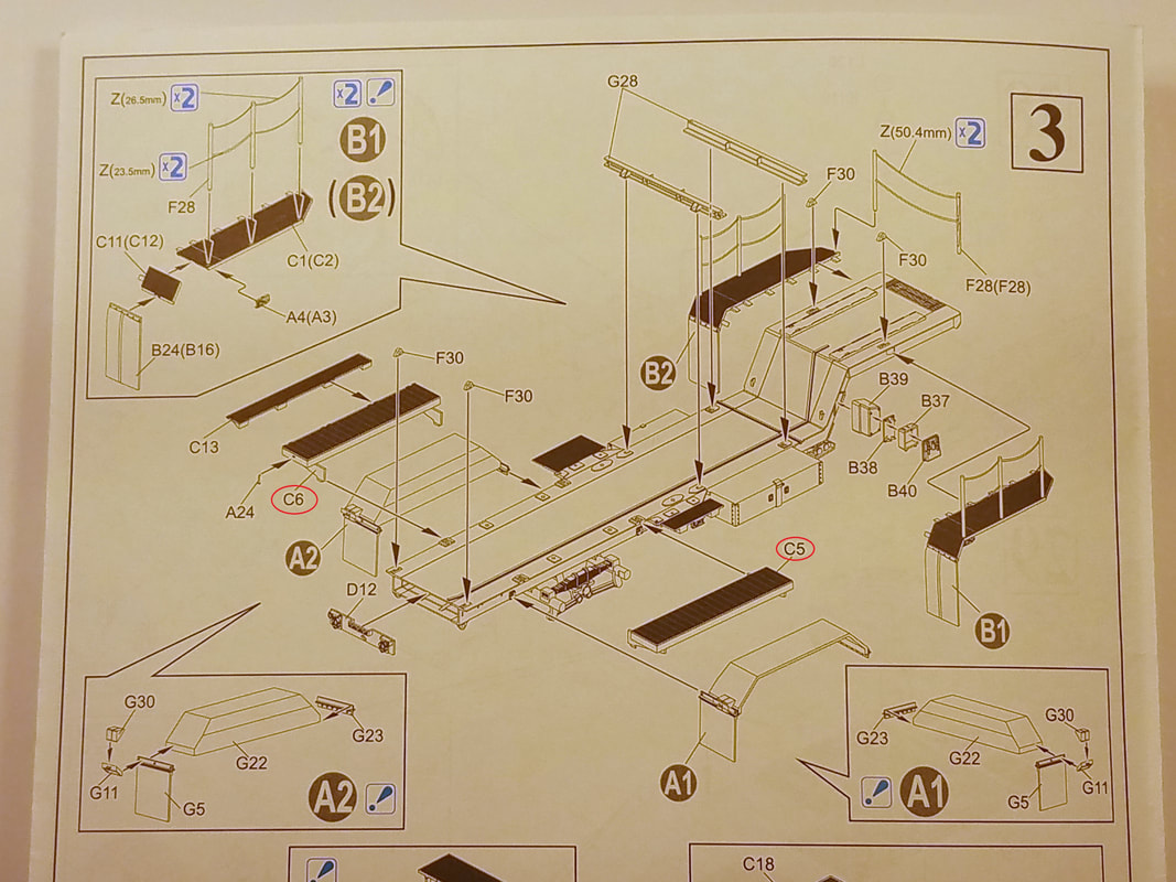
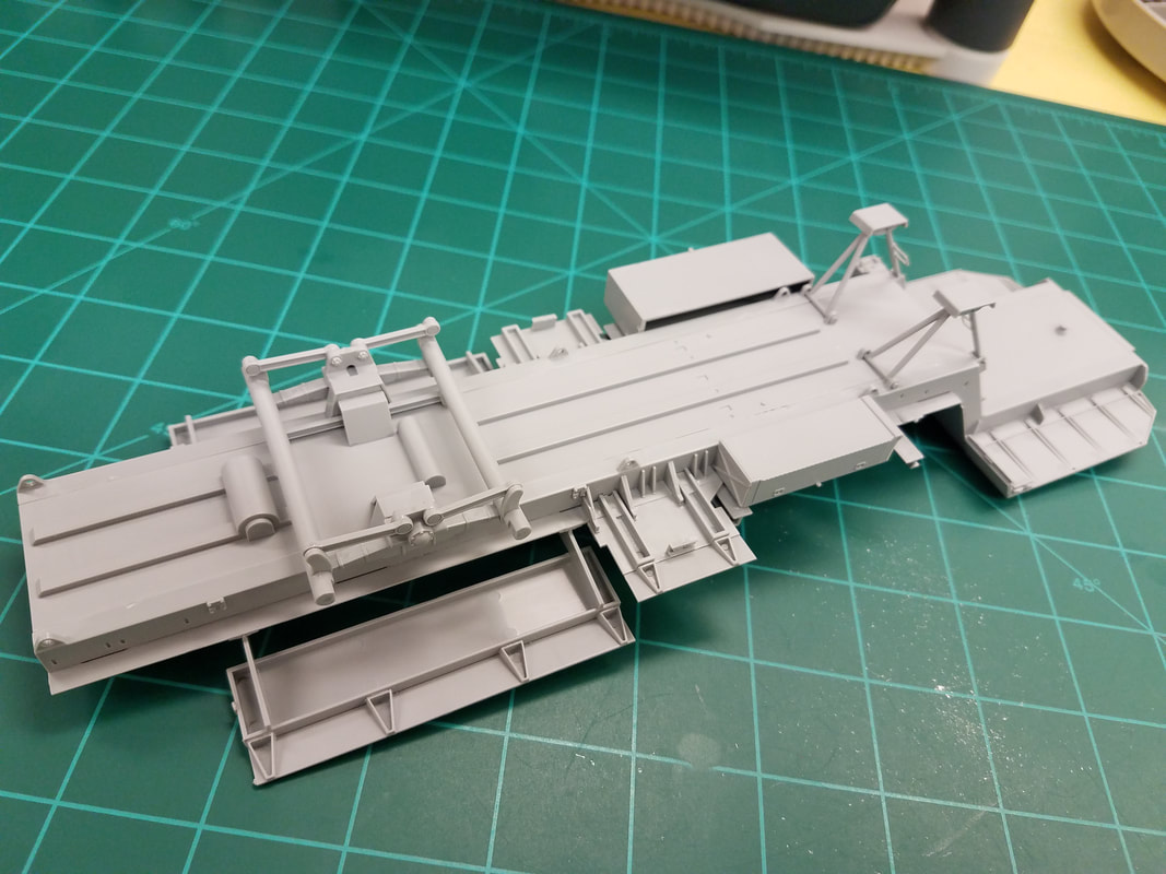
The front mud flaps can wait till later since they will be painted black but the rear flaps support the fenders and have to be glued to them now to confirm they fit to the chassis. I will leave the fenders off for painting separately since they cover the suspension too much. Speaking of fit, you need to trim the fender supports slightly to fit the “L” shaped embossing on the chassis. Part G23 mounts with the three boltheads facing out. Leave parts G30 (wheel chocks) off till final construction. And another numbering snafu: parts C5 and C6 are reversed, just match the hinges on part C13. Here is the trailer after Step 3 [8, 9, 10].
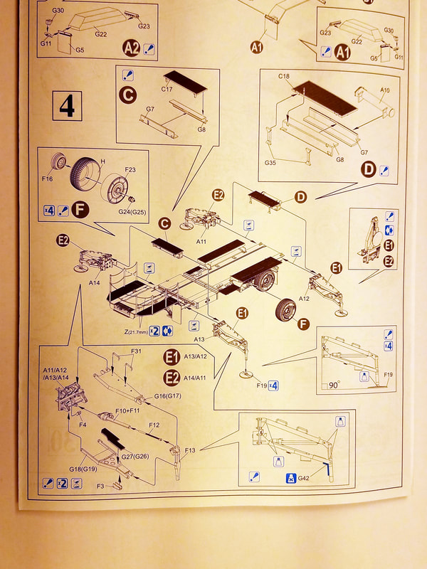
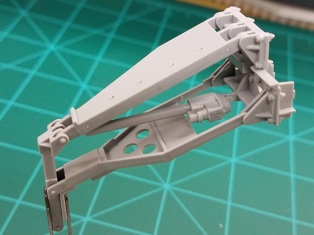
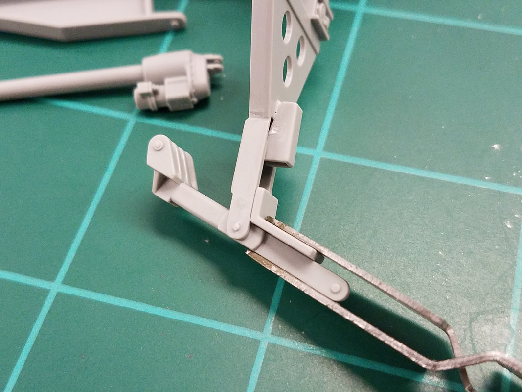
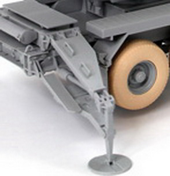
On to Step 4 [7]. OK, they show the corner cable railings as optional here but there is still not enough wire to do both upper and lower ones so just ignore this. Now this step basically covers the outriggers and, in typical Dragon fashion, it is confusing and incomplete. Apparently you can build the outriggers fixed in either the stowed or deployed position. Since I won't be attaching them to the chassis until after painting, I'll do deployed and see how that goes. For the wheels, I'll assemble them except for the front hub (F16), paint the whole thing tire black, and add the front hub later. You can paint the rear hub on F23 differently if you like but it is hidden by the suspension. Numbering snafu again: the tires are type M, not H. Alright, I've dry assembled one just for grins [11] and here's what I found. There is only one actual pin/hole joint (G18/F13). The rest are just a pin, or tab, and a slot – no fixed pivot point. This makes alignment more difficult but if you move quickly you can get all the pieces glued together and tweak the joints until they are square. To help with this, they give you a 'template' piece that has the correct angle for the G18/F13 joint [12]. I'll start there and work backwards, leaving the footpad for final assembly to be sure it sits flat.
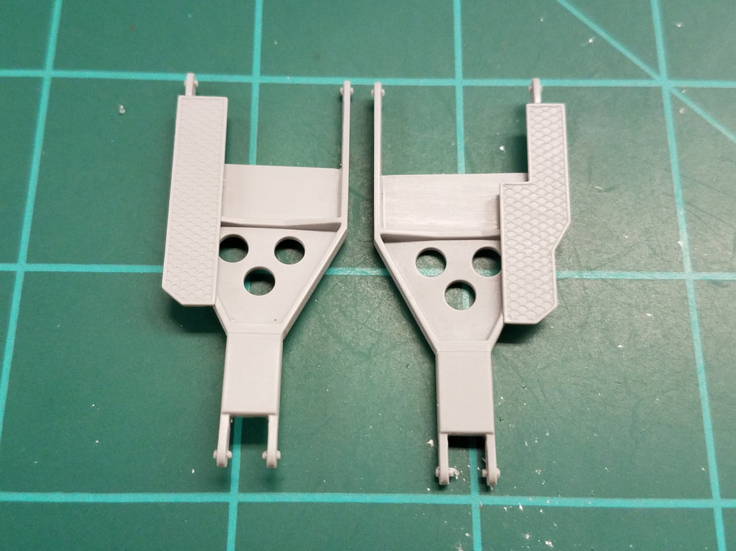
This next issue really had me confused but after much trial & error plus an internet search, I think I have it figured out. The gratings G26/G27 are totally hosed in the instructions. Not only do they not fit in the middle of the G18/G19, they are shown reversed. The beveled end goes toward F13 [13, left, right]. You also need to trim just a little bit from the lip on the underside to the grating so it sits flat. Also the part numbers are all mixed up. Here is the assembly sequence that will work:
First add the part number to back of A11/A12/A13/A14 with a Sharpie near ejector pin marks
Glue G26 to G18 x2 (trim underside a bit)
Glue G27 to G19 x2 (trim underside a bit)
Glue F3 and F4 to G18/G19 and A11/A12/A13/A14 respectively x4
Glue F13 to G18/G19 using G42 as a guide (no glue) and leave guide attached for remaining steps
Glue F10 to F11 x4
Glue G18 and G17 to A11
Glue G18 and G17 to A14
Glue G19 and G16 to A12
Glue G19 and G16 to A13
Insert F12 into F10/F11 x4 (no glue)
Glue F10/F11/F12 to A11/A12/A13/A14 and F12 to F13
Add F31 x2 x4
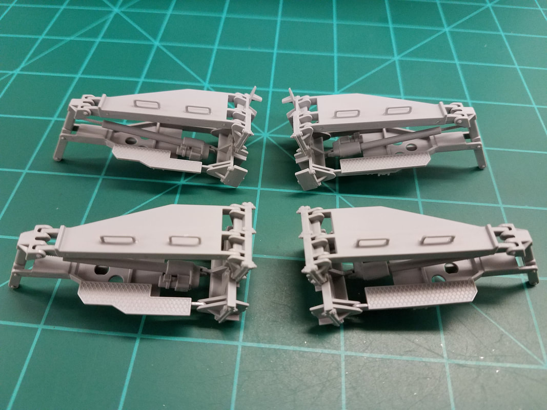
Oh, and if you can get all 4 parts F12 cut from the sprue and trimmed without breaking them you are a better man than I am, Gunga Din. The assembled outriggers should look like this when complete [14,15]. The two cross platforms had no issues and will be set aside till after painting.
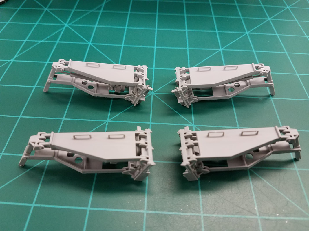
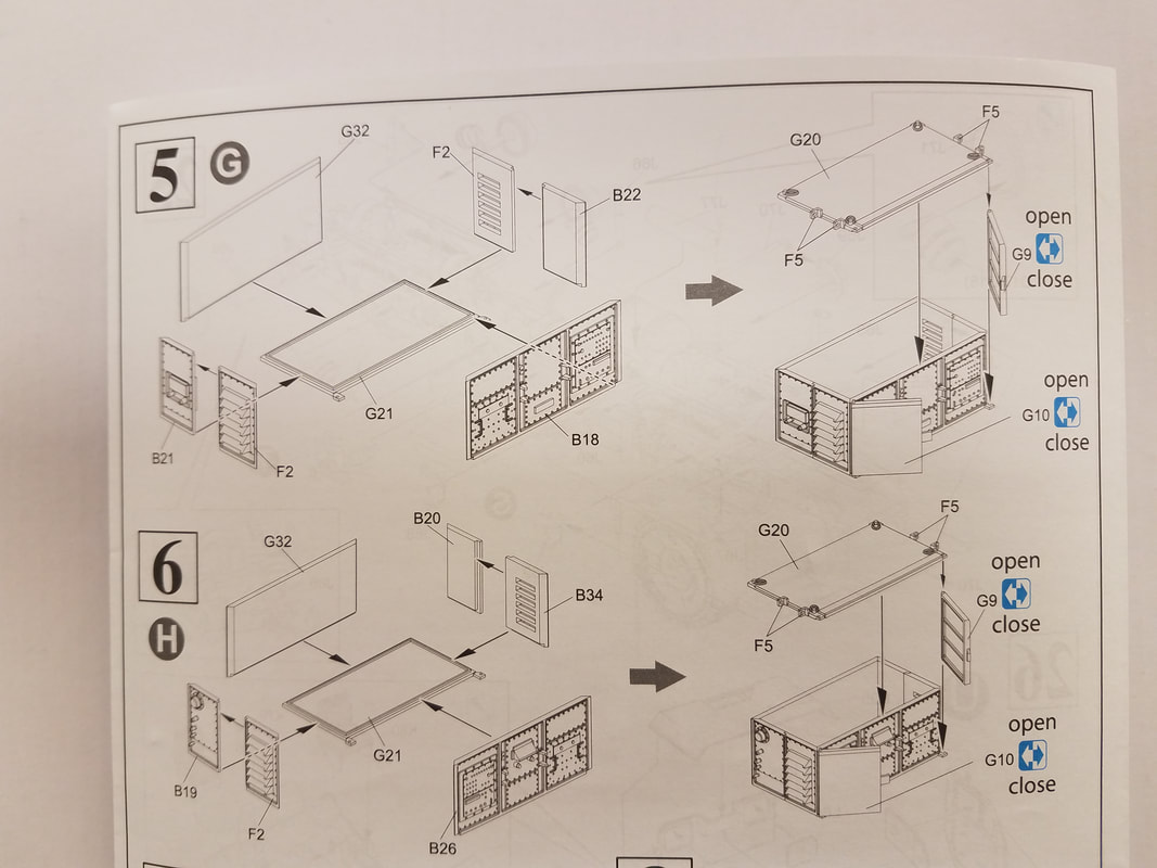
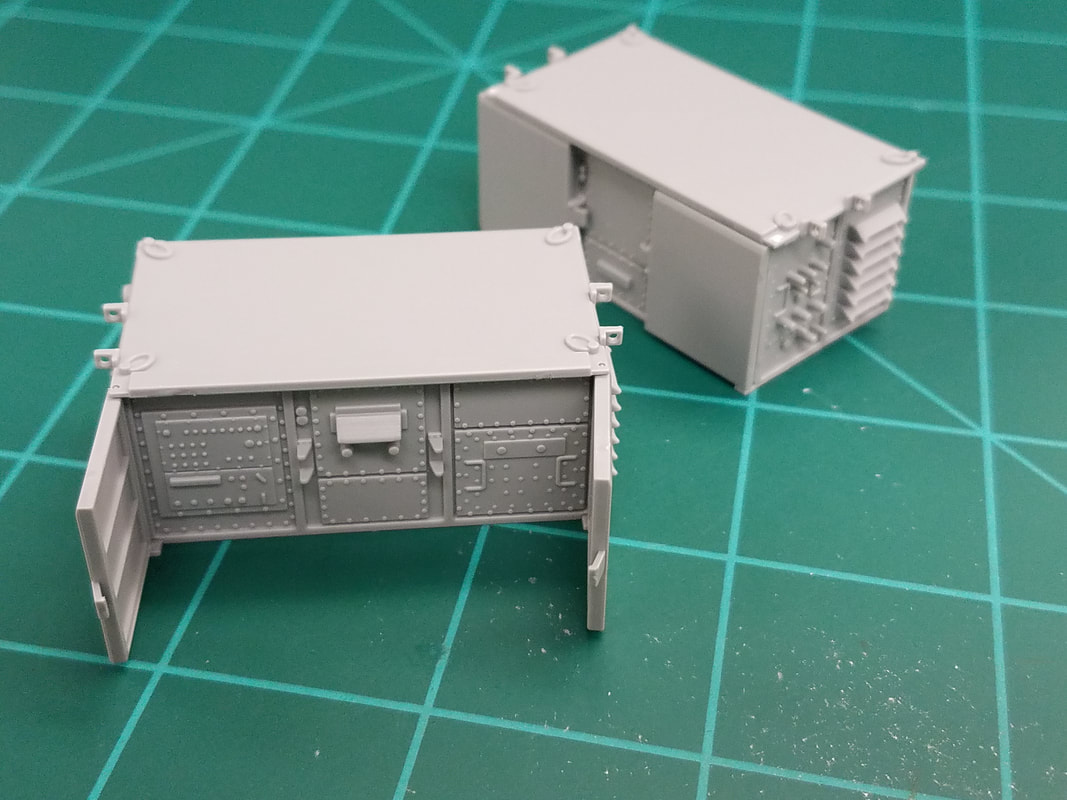
Steps 5 & 6 are the control modules [16]. While they look pretty easy, I suggest gluing the two end doors together on a flat surface then stand them up and glue the two sides to them, again on a flat surface. Set the four sides on the base, check for square, and then glue. Finally add the doors (open or closed optional) and set the top on. The doors should be movable. Now glue it on and set them aside to be painted separately [17].
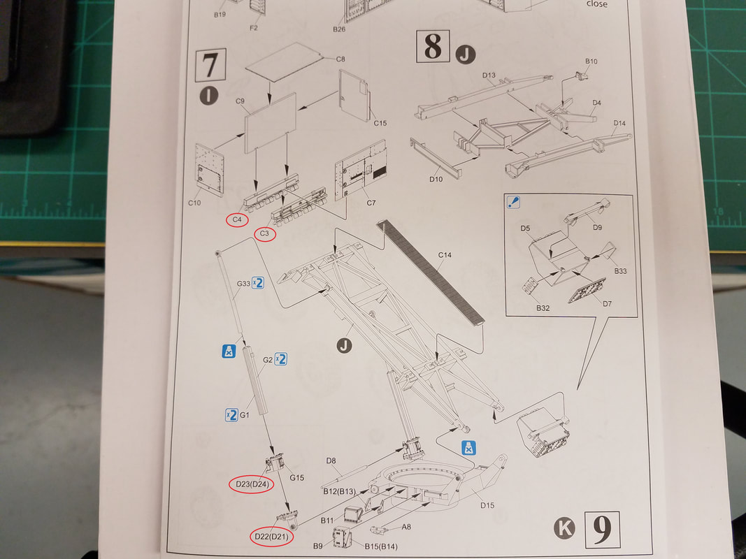
Step 7 starts off with another part number error: C3 and C4 are reversed [18]. You can verify this by placing them on the trailer, locating pins are toward the rear. Use the same assembly technique on this module as you did on the previous ones and set it aside for separate painting [19].
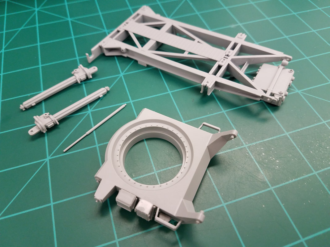
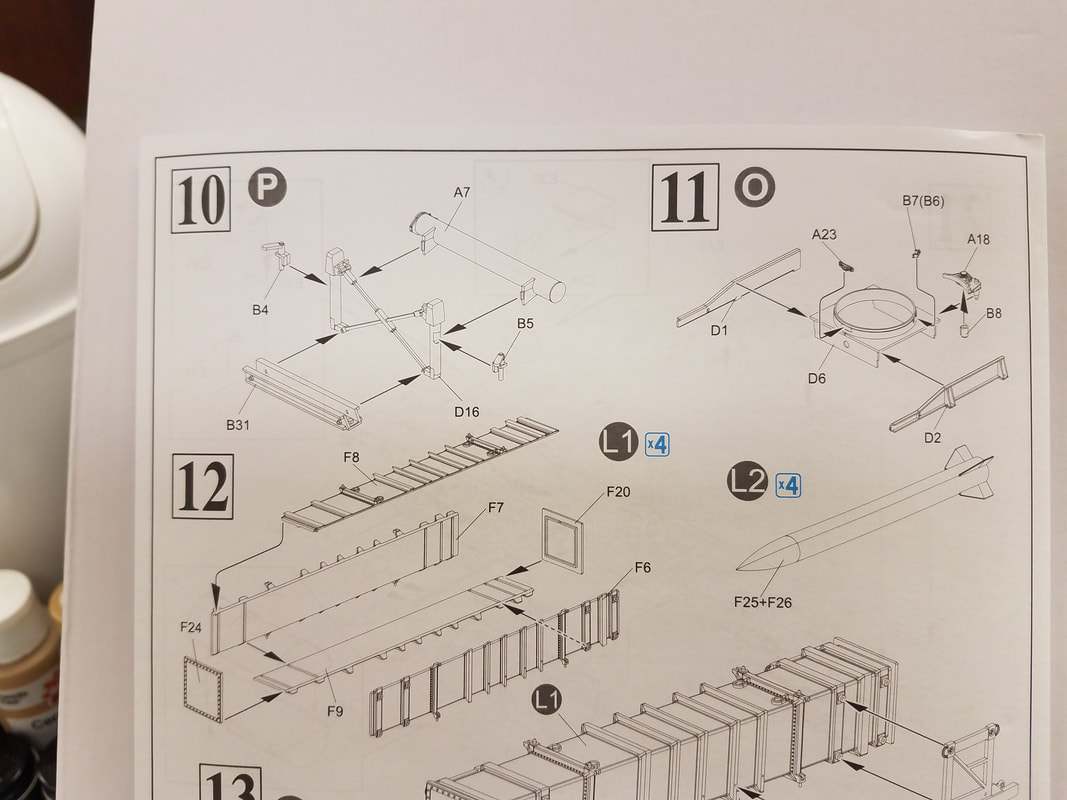
Steps 8 & 9 begin the missile pod frame assembly. Step 8 is no problem (for a change) [20] however step 9 has another numbering snafu: D21 goes with D23 and D22 goes with D24. A couple suggestions: attach the brackets to parts B9 and B11 and then glue them to the base frame. Also, trim the ribs off parts G33. Otherwise they fit really tight in the cylinders. For ease of painting I will keep the support base and frame pieces separate for now [21]. Steps 10 & 11 are small sub-assemblies [22] and pretty simple [23].
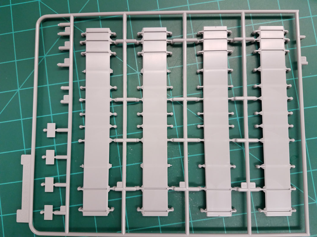
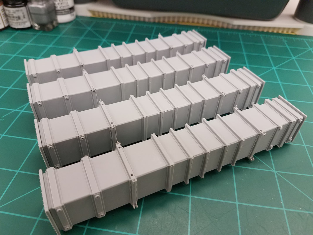
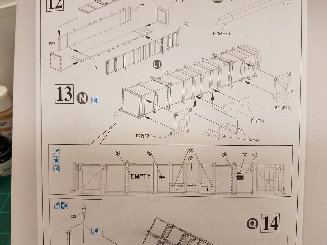
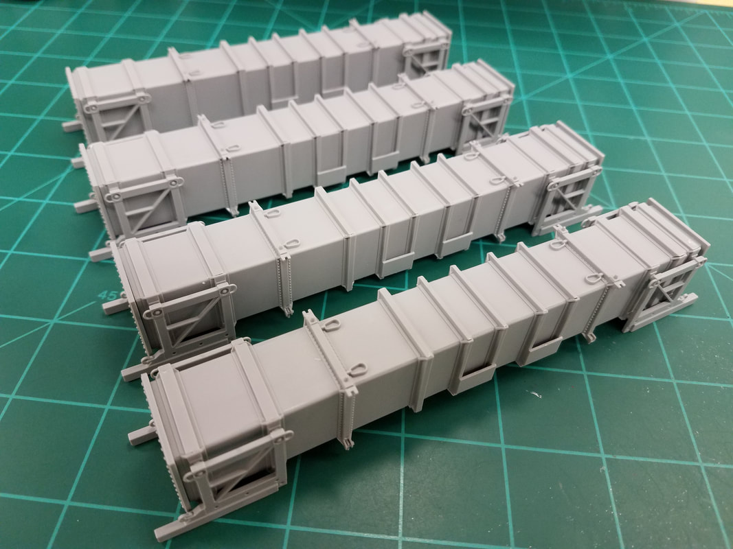
Step 12 begins the missiles and pods themselves. In military terms, this is what they refer to as a Charlie-Foxtrot [24]. You can see all the ejector pins and sprue gates on both sides of all four pieces of the missile pods. There are four of these pods. That's 88 trims per pod x 4 pods equals 352 spots to clean up. And it gets even better. Note that the inside [25] has two angles and the outside edge is rounded slightly [26]. Careful trimming is required so as to not leave a gap at the tip when two adjacent pieces are fitted together. I have dry-fitted one pod together [27] and you can see what I mean about the gap. When glued I can compensate for this a bit but it certainly will need some filler. I've only cleaned up one pod and this is the worst side on it. I have a technique now for the other three pods that preserves the angles better but this step is going to be a royal PITA. Something else to note, it is nearly impossible to glue the four sides together, align the ribs, and keep it square without some help. I took a 5” long piece of masking tape and split it lengthwise to wrap around the pod near both ends. Now I can glue the ends with endcaps and most of the middle of the pod. After letting it set for a bit, I will remove the tape and finish gluing. I don't want glue to seep under the tape. Here are the assembled pods at this point [28].
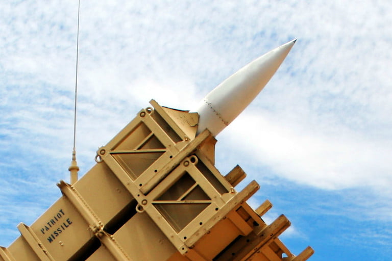
As I mentioned earlier, the missiles do not fit inside the pods without trimming some from the fins (they go corner-to-corner). This is OK since you can't see them anyway if you are showing a launch but there is a better way. In a real launch, the missile penetrates the end of the pod while the frame remains intact [launch]. You could cut one missile behind the nosecone, glue it to the endcap, and make paper or tissue flaps to simulate the broken membrane. Just a thought. Here are the assembled missiles [29] and a painting guide [missile paint].
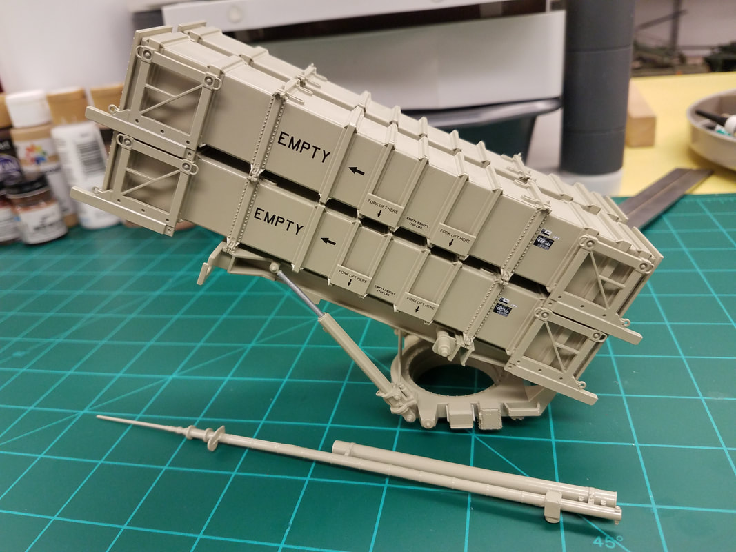
Step 13 [30] completes the individual pods and shows the decal placement which will come after painting. These are the completed pods [31] ready for the paint shop.
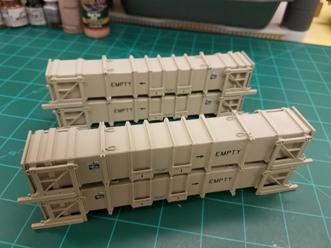
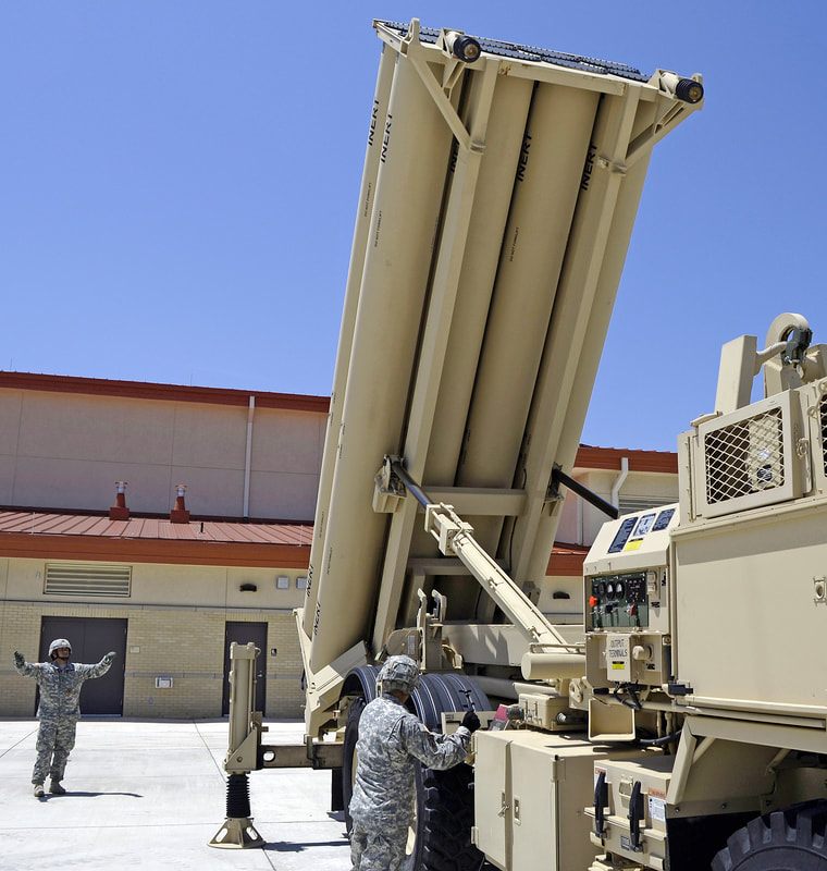
I am going to use a monochrome desert sand color for the entire model similar to this THAAD photo [paint]. You may want to use the NATO three-tone camo or something completely different. There are numerous photos on the web that you can go by. I've been using rattle cans since forever so that is what I am most comfortable with. In this case, the best match for desert sand I have found is Rustoleum Satin Fossil. It dries to the touch in an hour or so and cures in 24 hours. After the spraying is dry I'll decant a little paint at a time and touch up spots by hand that I missed or that were hidden. This takes time and a steady hand but it works for me.
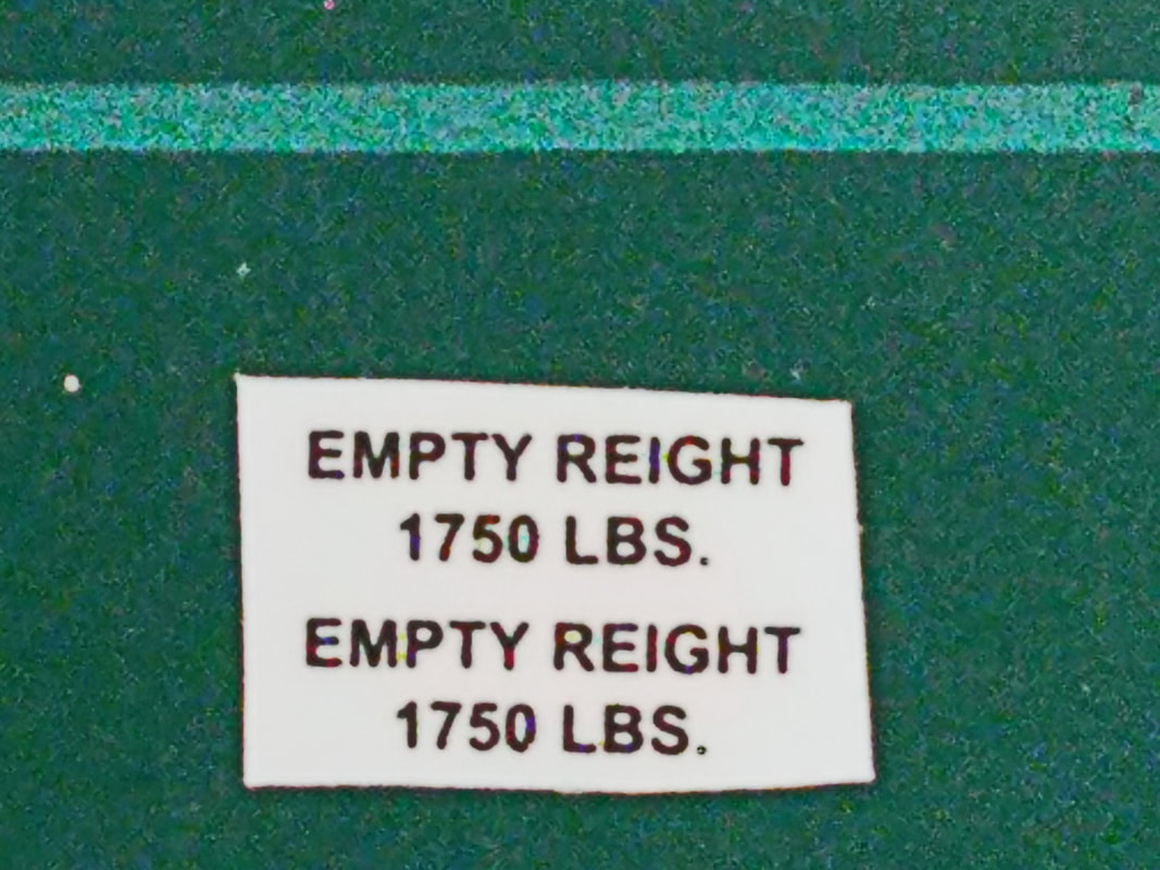
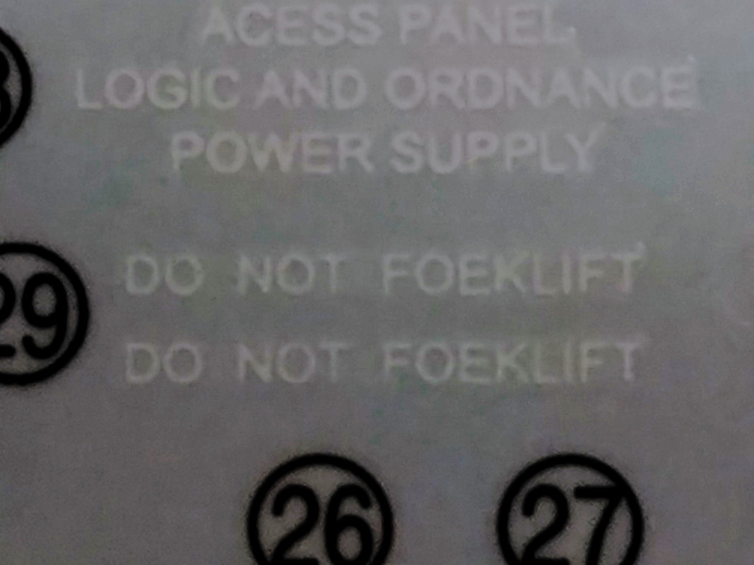
Now for a little Chinese decal humor [L1, L2]. You want some Flied Lice with that? Make up your own joke about a “Foek Lift”. Even the decals in this kit have a snafu.
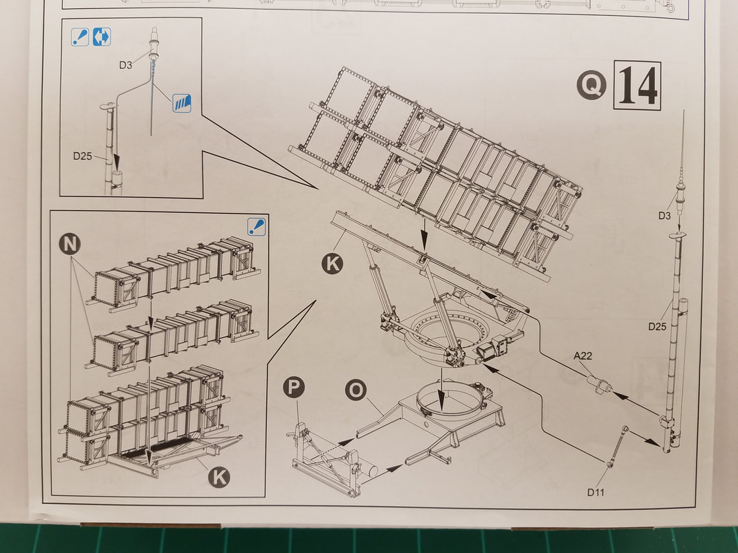
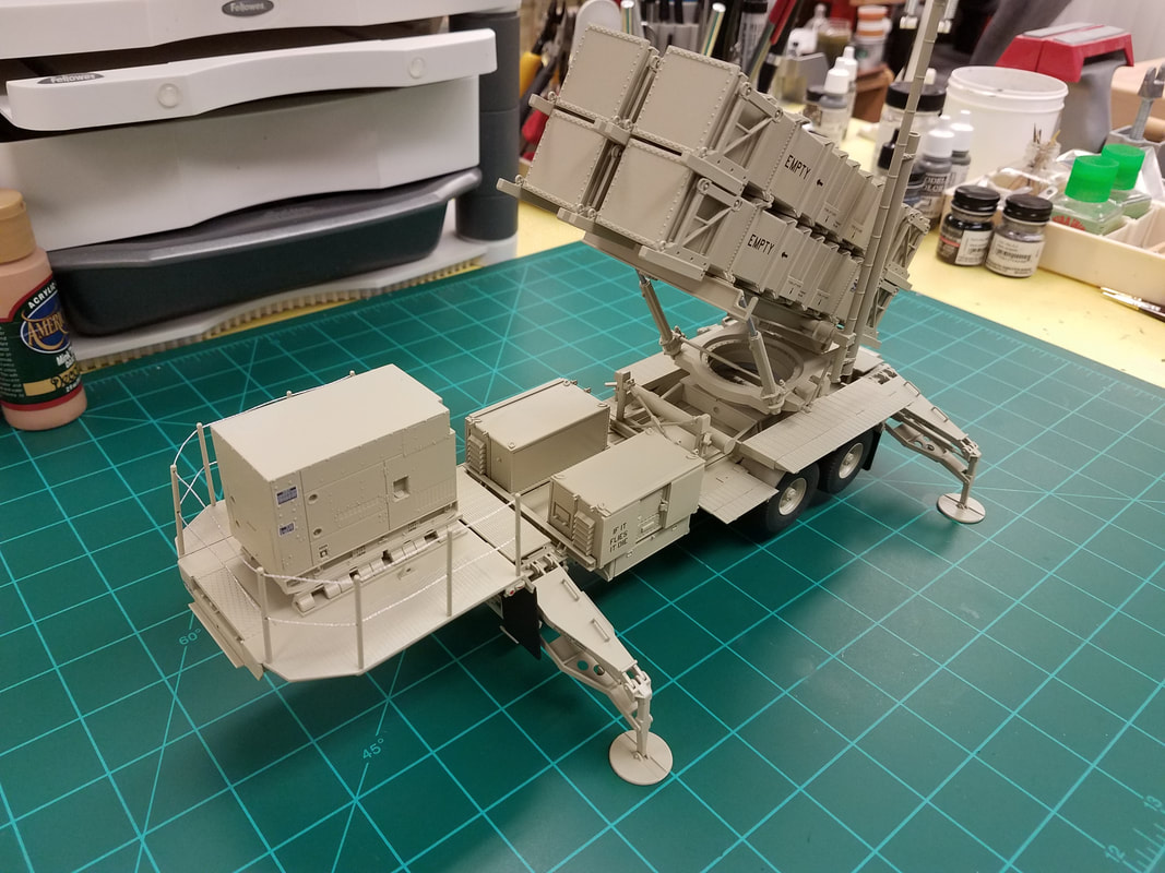
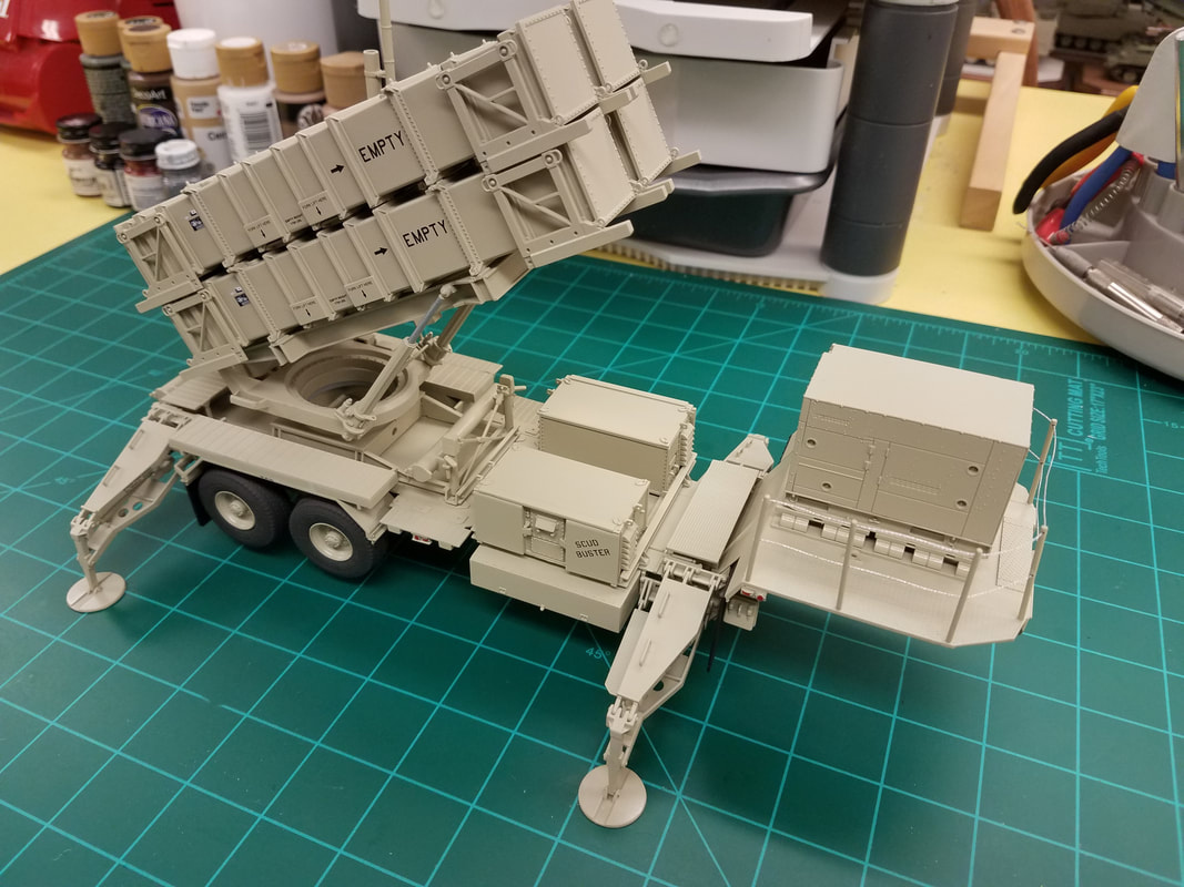
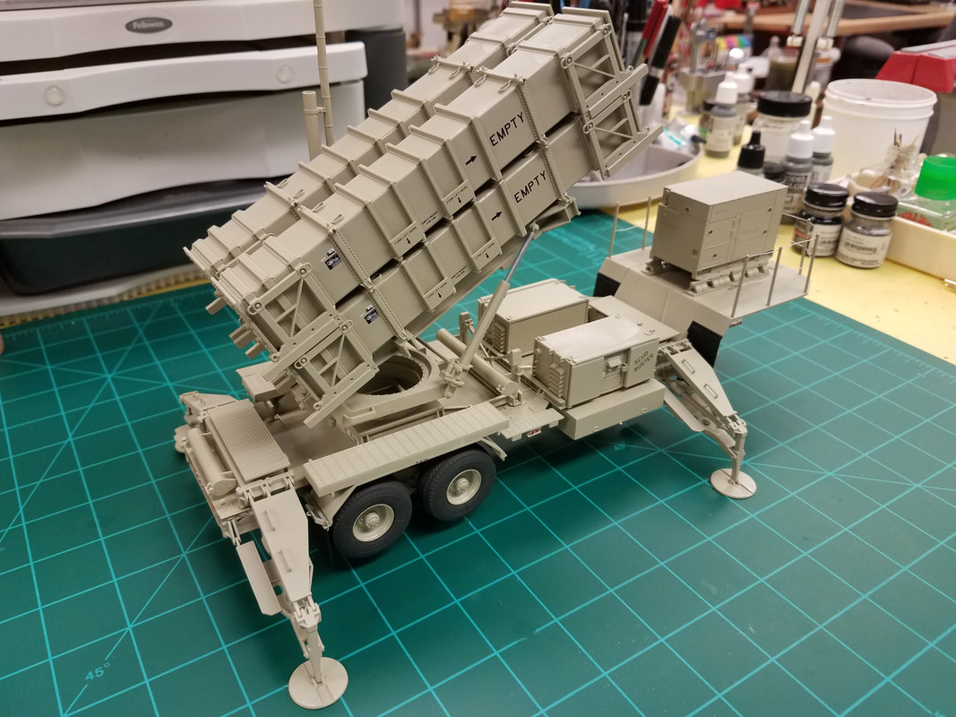
Back to modeling, here are the pods painted and decaled [32]. Step 14 [33] assembles the four pods together along with the lifting frame and antenna. I glued O and P in the chassis, built the antenna, and combined the N and K assemblies which will be attached later [34]. You are now able to take all those parts we left off earlier and finishing the chassis. In order, I did the fenders, wheels, outriggers, cabinets, and finally the rail stanchions. Be sure to orient the stanchion holes correctly. Finally I used silver thread for the railings, attached the antenna to the pod assembly, and placed it on the trailer. A little touchup painting and detailing the reflectors and I'll call this build done [35,36,37,38]. Now on to the HEMTT.
Ok, call me crazy but I'm starting the Dragon “Black Death” . . . er, “Black Label” Patriot PAC-1 w/HEMTT [1]. The Patriot system was (is) built down in Camden, at least partially now, so there is an Arkansas connection. They also build the M270-A1 MLRS, THAAD, and HIMARS down there, among other things. I'm hoping the kit does not live up to the Black Label reputation but we'll see. It's a big box with about 530 pieces on 13 light gray sprues, one clear sprue, a small decal sheet and Dragon DS tires (Boo-Hiss). Also a short length of braided stainless wire but no photoetch – rather unusual for a 2017 kit. The M983 HEMTT is actually the old Italeri M977 kit from maybe 20 years ago with a few part changes. If you are looking for accuracy in this kit, forget it. The kit sells for between $100 and $150 now. I gave $117 for it back in 2017. The instructions are typical Dragon – busy, incomprehensible, vague, mis-numbered in several places, and a bit out of sequence. Wait, this is supposed to be a “Smart Kit”. Guess that means you had better be pretty smart to figure out how to build it. A number of in-box reviews and sprue photos are available on the net so I won't waste space here duplicating them. Take a look out there if you are interested.
The first 15 steps are to build the trailer and launch system including four missiles (which do not appear to be able to fit into the weapon pods ??), with steps 16-30 being for the HEMTT. I'll probably display the missiles separately anyway. I usually build a kit in sub-assemblies to make painting easier so bear with me as I jump around some in the instructions. So, let's get started with the trailer.
Right from the start [2] you have to decide whether you want to display the PAC-1 in the travel or launch position. While the pods can be made movable (supposedly), in Step 1 the trailer skids must be posed folded or extended. Your choice. Mine will be extended. I hope attaching them to the chassis now rather than later in the build doesn't get them broken. That said, there is a parts numbering snafu in this very first step. The chassis side rails are parts B30(B2) not G30(G2). This does not bode well for the rest of the build. Here is the trailer bed with the skids attached [3]. Step 2 [4] adds some suspension and storage parts to the chassis. And another numbering snafu – one part B36 should be B35. All these pieces went together without a problem though[5].
Beginning with Step 3 [6] things start to get interesting. Note you will need just over 192mm (measured straight, hole-to-hole) of the braided wire to make the top cable railing. They give you 240mm so that should be enough. But wait, you have TWO cable railings. Somebody forgot to include enough wire to do both. So you have a choice: omit the railings entirely or use something else for the cables. I will do the latter since I won't be installing the cables until after painting anyway. I have some braided silver thread that is about the right size and can replicate the sag better anyway.
The front mud flaps can wait till later since they will be painted black but the rear flaps support the fenders and have to be glued to them now to confirm they fit to the chassis. I will leave the fenders off for painting separately since they cover the suspension too much. Speaking of fit, you need to trim the fender supports slightly to fit the “L” shaped embossing on the chassis. Part G23 mounts with the three boltheads facing out. Leave parts G30 (wheel chocks) off till final construction. And another numbering snafu: parts C5 and C6 are reversed, just match the hinges on part C13. Here is the trailer after Step 3 [8, 9, 10].
On to Step 4 [7]. OK, they show the corner cable railings as optional here but there is still not enough wire to do both upper and lower ones so just ignore this. Now this step basically covers the outriggers and, in typical Dragon fashion, it is confusing and incomplete. Apparently you can build the outriggers fixed in either the stowed or deployed position. Since I won't be attaching them to the chassis until after painting, I'll do deployed and see how that goes. For the wheels, I'll assemble them except for the front hub (F16), paint the whole thing tire black, and add the front hub later. You can paint the rear hub on F23 differently if you like but it is hidden by the suspension. Numbering snafu again: the tires are type M, not H. Alright, I've dry assembled one just for grins [11] and here's what I found. There is only one actual pin/hole joint (G18/F13). The rest are just a pin, or tab, and a slot – no fixed pivot point. This makes alignment more difficult but if you move quickly you can get all the pieces glued together and tweak the joints until they are square. To help with this, they give you a 'template' piece that has the correct angle for the G18/F13 joint [12]. I'll start there and work backwards, leaving the footpad for final assembly to be sure it sits flat.
This next issue really had me confused but after much trial & error plus an internet search, I think I have it figured out. The gratings G26/G27 are totally hosed in the instructions. Not only do they not fit in the middle of the G18/G19, they are shown reversed. The beveled end goes toward F13 [13, left, right]. You also need to trim just a little bit from the lip on the underside to the grating so it sits flat. Also the part numbers are all mixed up. Here is the assembly sequence that will work:
First add the part number to back of A11/A12/A13/A14 with a Sharpie near ejector pin marks
Glue G26 to G18 x2 (trim underside a bit)
Glue G27 to G19 x2 (trim underside a bit)
Glue F3 and F4 to G18/G19 and A11/A12/A13/A14 respectively x4
Glue F13 to G18/G19 using G42 as a guide (no glue) and leave guide attached for remaining steps
Glue F10 to F11 x4
Glue G18 and G17 to A11
Glue G18 and G17 to A14
Glue G19 and G16 to A12
Glue G19 and G16 to A13
Insert F12 into F10/F11 x4 (no glue)
Glue F10/F11/F12 to A11/A12/A13/A14 and F12 to F13
Add F31 x2 x4
Oh, and if you can get all 4 parts F12 cut from the sprue and trimmed without breaking them you are a better man than I am, Gunga Din. The assembled outriggers should look like this when complete [14,15]. The two cross platforms had no issues and will be set aside till after painting.
Steps 5 & 6 are the control modules [16]. While they look pretty easy, I suggest gluing the two end doors together on a flat surface then stand them up and glue the two sides to them, again on a flat surface. Set the four sides on the base, check for square, and then glue. Finally add the doors (open or closed optional) and set the top on. The doors should be movable. Now glue it on and set them aside to be painted separately [17].
Step 7 starts off with another part number error: C3 and C4 are reversed [18]. You can verify this by placing them on the trailer, locating pins are toward the rear. Use the same assembly technique on this module as you did on the previous ones and set it aside for separate painting [19].
Steps 8 & 9 begin the missile pod frame assembly. Step 8 is no problem (for a change) [20] however step 9 has another numbering snafu: D21 goes with D23 and D22 goes with D24. A couple suggestions: attach the brackets to parts B9 and B11 and then glue them to the base frame. Also, trim the ribs off parts G33. Otherwise they fit really tight in the cylinders. For ease of painting I will keep the support base and frame pieces separate for now [21]. Steps 10 & 11 are small sub-assemblies [22] and pretty simple [23].
Step 12 begins the missiles and pods themselves. In military terms, this is what they refer to as a Charlie-Foxtrot [24]. You can see all the ejector pins and sprue gates on both sides of all four pieces of the missile pods. There are four of these pods. That's 88 trims per pod x 4 pods equals 352 spots to clean up. And it gets even better. Note that the inside [25] has two angles and the outside edge is rounded slightly [26]. Careful trimming is required so as to not leave a gap at the tip when two adjacent pieces are fitted together. I have dry-fitted one pod together [27] and you can see what I mean about the gap. When glued I can compensate for this a bit but it certainly will need some filler. I've only cleaned up one pod and this is the worst side on it. I have a technique now for the other three pods that preserves the angles better but this step is going to be a royal PITA. Something else to note, it is nearly impossible to glue the four sides together, align the ribs, and keep it square without some help. I took a 5” long piece of masking tape and split it lengthwise to wrap around the pod near both ends. Now I can glue the ends with endcaps and most of the middle of the pod. After letting it set for a bit, I will remove the tape and finish gluing. I don't want glue to seep under the tape. Here are the assembled pods at this point [28].
As I mentioned earlier, the missiles do not fit inside the pods without trimming some from the fins (they go corner-to-corner). This is OK since you can't see them anyway if you are showing a launch but there is a better way. In a real launch, the missile penetrates the end of the pod while the frame remains intact [launch]. You could cut one missile behind the nosecone, glue it to the endcap, and make paper or tissue flaps to simulate the broken membrane. Just a thought. Here are the assembled missiles [29] and a painting guide [missile paint].
Step 13 [30] completes the individual pods and shows the decal placement which will come after painting. These are the completed pods [31] ready for the paint shop.
I am going to use a monochrome desert sand color for the entire model similar to this THAAD photo [paint]. You may want to use the NATO three-tone camo or something completely different. There are numerous photos on the web that you can go by. I've been using rattle cans since forever so that is what I am most comfortable with. In this case, the best match for desert sand I have found is Rustoleum Satin Fossil. It dries to the touch in an hour or so and cures in 24 hours. After the spraying is dry I'll decant a little paint at a time and touch up spots by hand that I missed or that were hidden. This takes time and a steady hand but it works for me.
Now for a little Chinese decal humor [L1, L2]. You want some Flied Lice with that? Make up your own joke about a “Foek Lift”. Even the decals in this kit have a snafu.
Back to modeling, here are the pods painted and decaled [32]. Step 14 [33] assembles the four pods together along with the lifting frame and antenna. I glued O and P in the chassis, built the antenna, and combined the N and K assemblies which will be attached later [34]. You are now able to take all those parts we left off earlier and finishing the chassis. In order, I did the fenders, wheels, outriggers, cabinets, and finally the rail stanchions. Be sure to orient the stanchion holes correctly. Finally I used silver thread for the railings, attached the antenna to the pod assembly, and placed it on the trailer. A little touchup painting and detailing the reflectors and I'll call this build done [35,36,37,38]. Now on to the HEMTT.