Build Log of the Modelcollect BAL-E
Coastal Defense Missile System
MZKT Chassis in 1/72 scale
By Richard Geraci
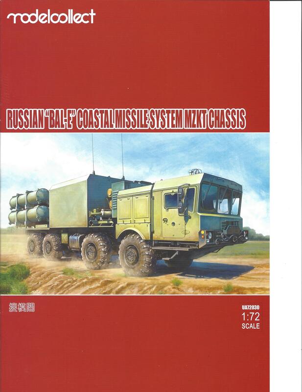
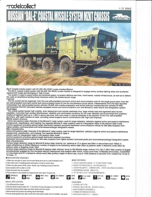
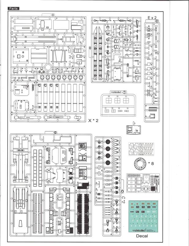
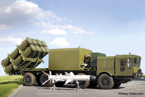
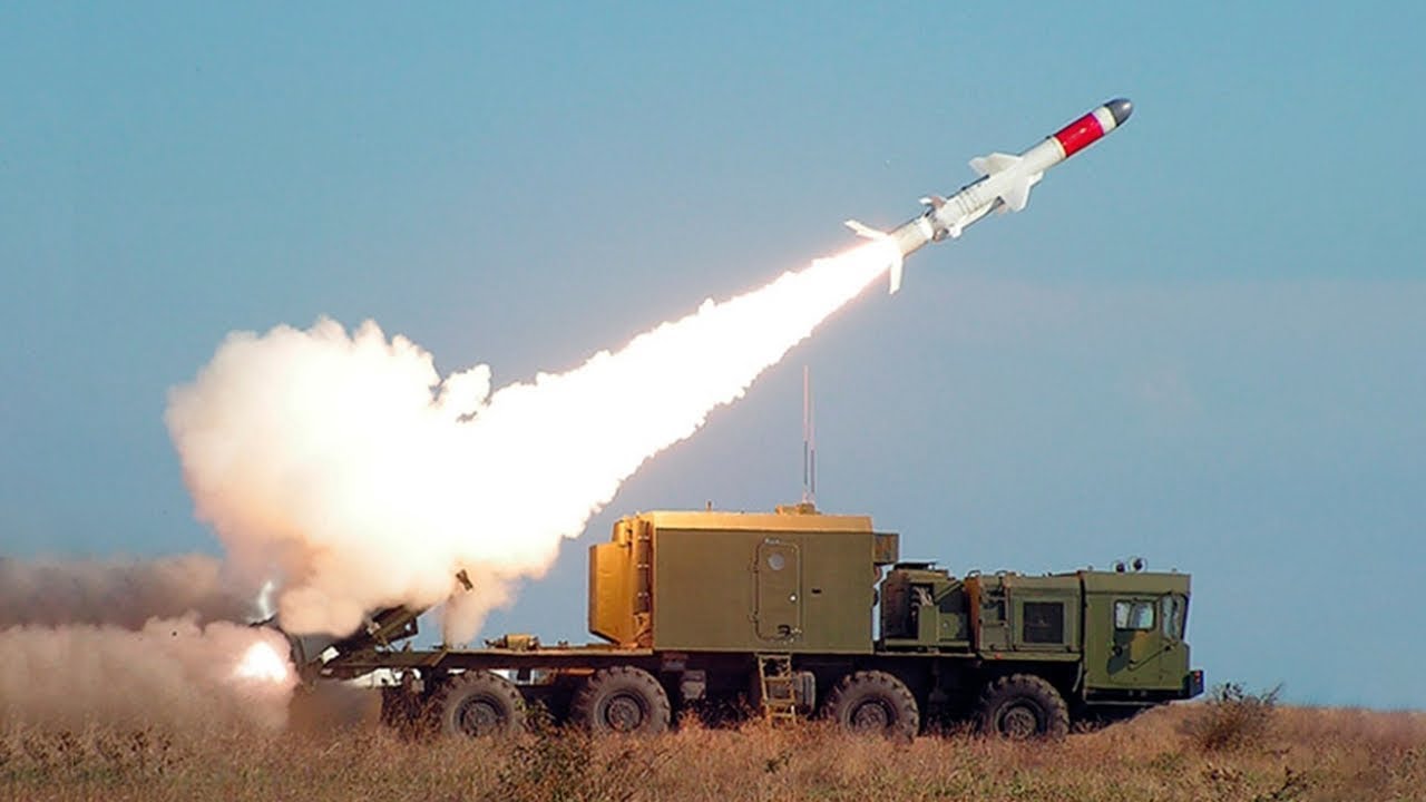
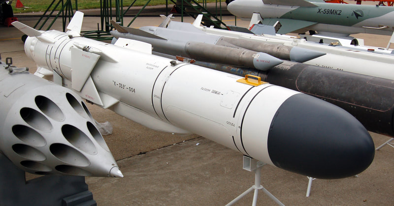
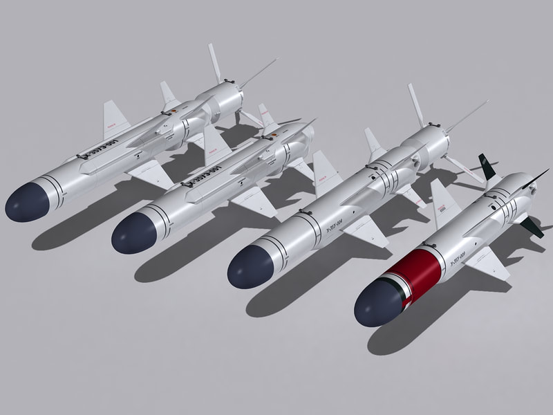
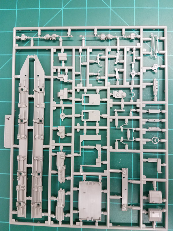
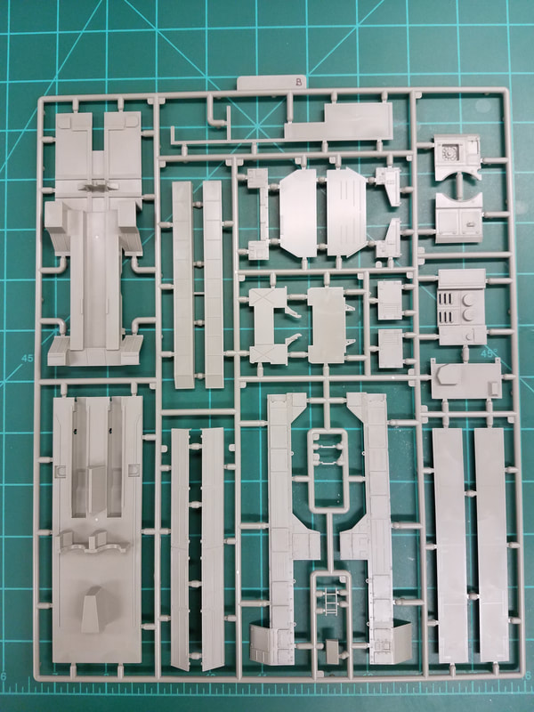
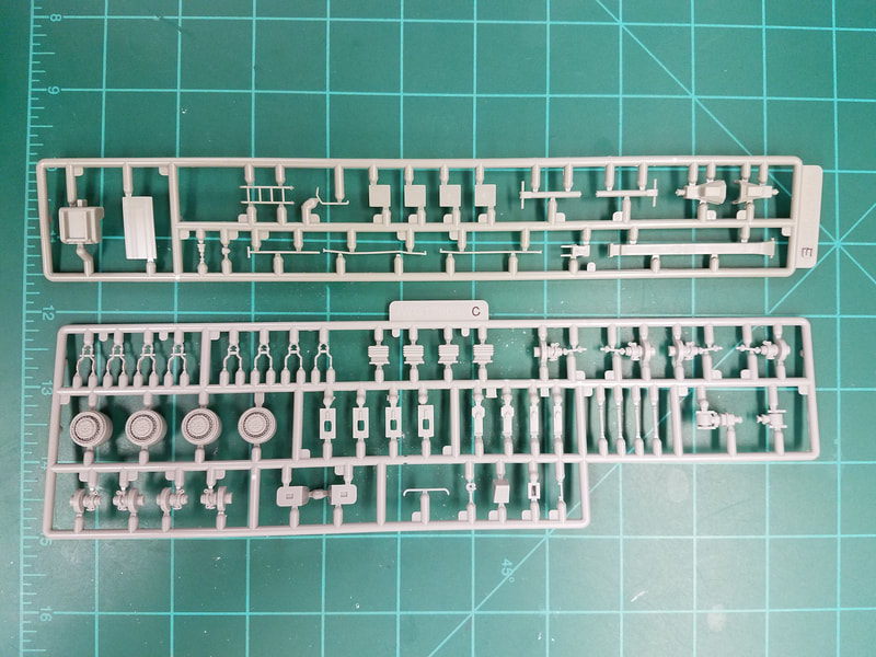
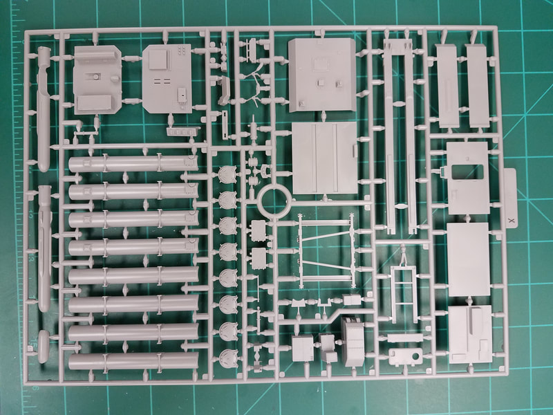
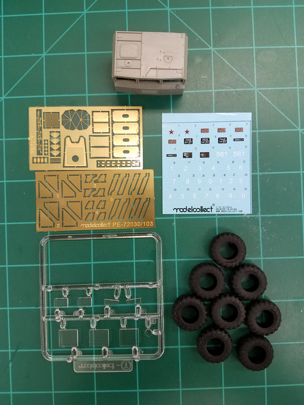
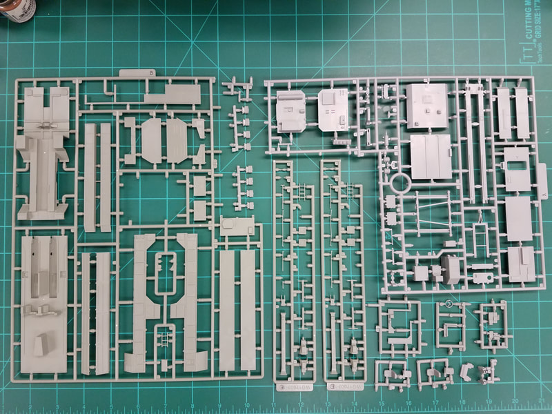
This is one of several Russian mobile missile system kits in 1/72 scale by the Chinese company Modelcollect [Iscan]. It is very detailed and has a lot of pieces for a model that is only 1.5” wide by 8” long. Included with the instructions is some interesting background info on the BAL-E [Iscan0001]. There are 8 sprues of gray plastic, one clear sprue, a separate cab, 8 rubber tires, 2 PE frets and a small decal sheet [Iscan0002]. Here are the pieces [spA, spB, spC-E, spX, spZ]. Note there are 2 cruise missiles with stands that can be displayed as separate items. I have included some photos of the real vehicle and missiles for reference [P1-P5]. One shows it in a darker green color and the other in the usual 4BO Russian green. There are other photos which depict it in a dark forest green, almost a black-green, so you could probably go with most anything except an olive drab and get by with it. The gray tip missile is the surface-surface type and the red banded one is the surface-air version.
At first glance, the build does not seem particularly difficult but having built four other versions on the MZKT and MAZ chassis I can tell you it is not easy. The suspension is particularly tricky and requires great care to not break the suspension arms and to get all 8 wheels in contact with the ground. Fair warning, step 6 may have you speaking Chinese or a variation of it. Remember, Patience is a Virtue.
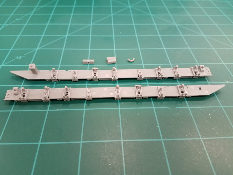
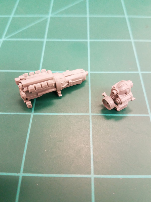
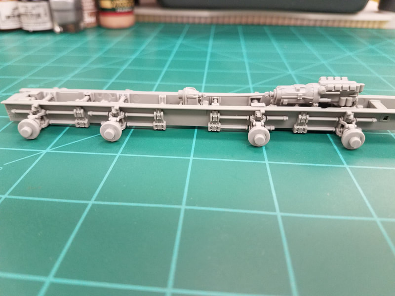
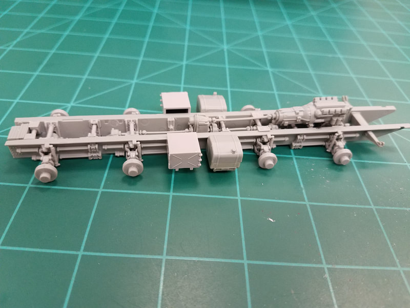
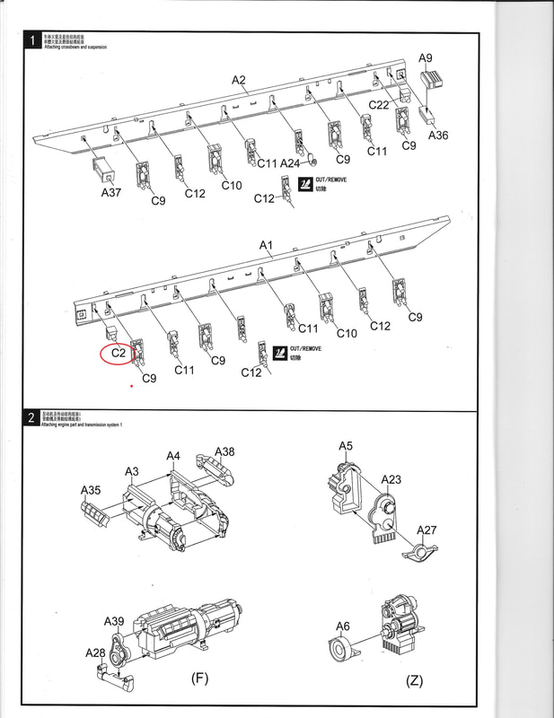
Step 1 [Iscan0003] builds the side frame rails and cross members. Note that the cross members will meet in the middle and do not have any locators on the ends of the rods. It is important that the frame rails sit flat on the bottom, are NOT vertical, and that the cross members are aligned across from each other. I have some Corelle ceramic cutting boards that are dead flat and glue won't stick to them. They make a good surface to ensure parts are flat and square as they are assembled. If you don't get this right, step 6 will be even harder. I suggest you leave parts A9, A24, and A36 off until after the sides are joined in step 5. Also a parts numbering snafu: part C2 is actually C22. Here are the assembled side rail frames [1]. Step 2 is the engine and differential. You need to enlarge the hole in A6 to fit all the way down on the A5 pin. Check the fit of the little side supports on A6/A27 with the locating nibs on A1/A2. Oh, and add a C20 hitch (not shown) to A36. Here are these parts assembled [2].
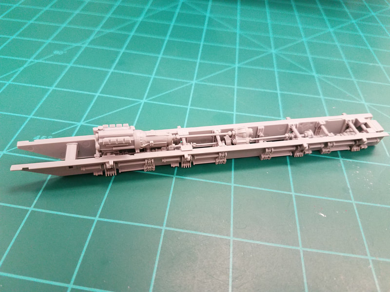
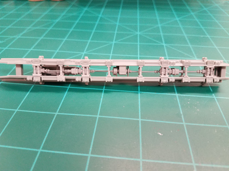
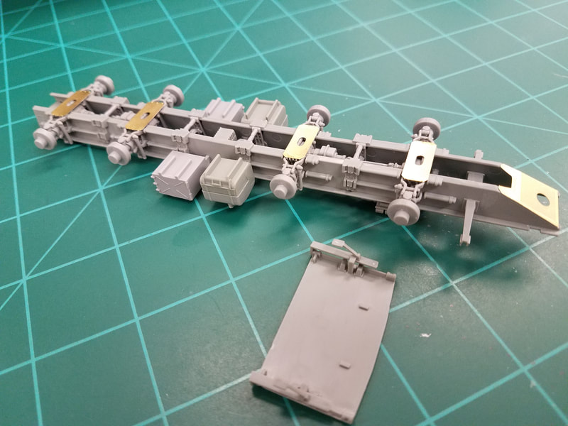
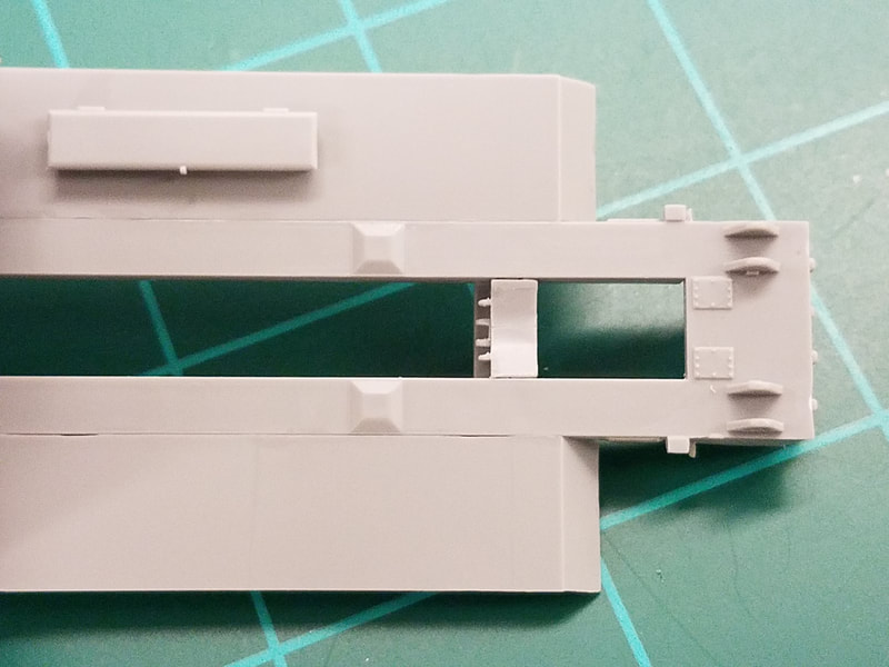
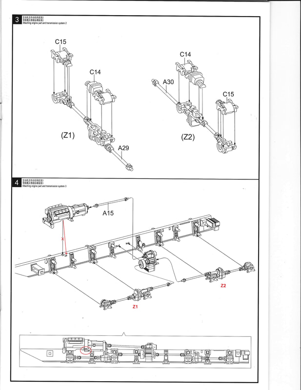
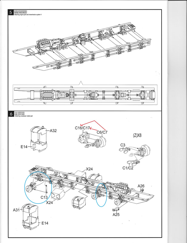
Step 3 builds the drive trains [Iscan0004] and Step 4 installs them along with the engine and differential. Note that the detail drawing shows the correct location for the rear engine mount while the main drawing is incorrect. I did not install the engine and A15 until after the sides were glued together in step 5. Now in Step 5 bring both sides together [Iscan0005] and install the engine and remaining parts from step 1. Take your time and check alignment as you go. You should end up with something like this [3,4].
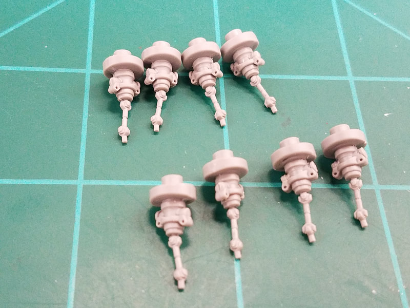
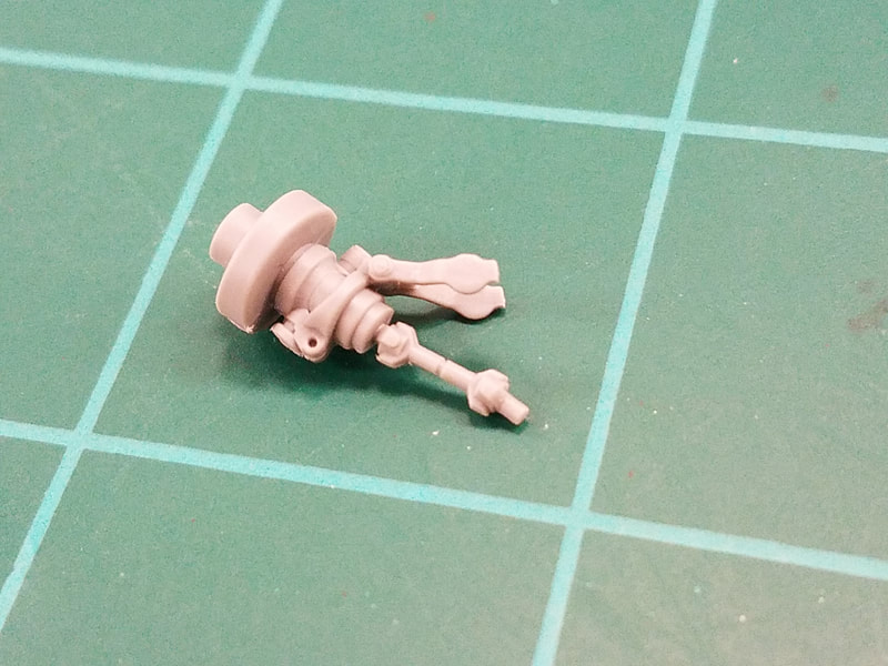
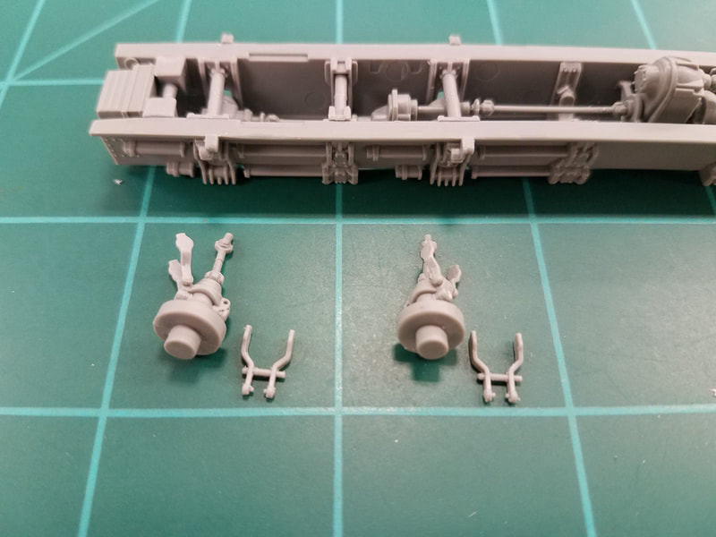
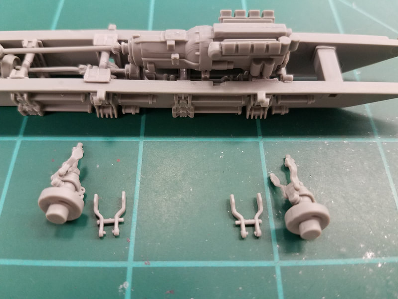
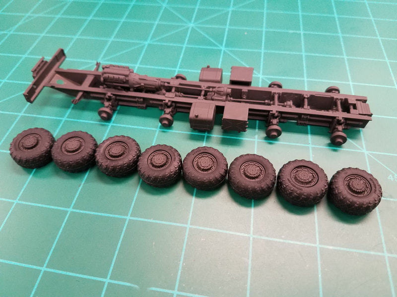
And now for the dreaded Step 6. The instructions are really messed up here so I'll step you through the assembly. First, parts C6 glue to parts C17. Parts C7 glue to parts C16. The assemblies are symmetrical and interchangeable but keep all the C6 on one side and the C7 on the other just the same [5]. Now with the short shaft pointing up, snap a C3 into the top holes. Be sure the little nibs on C3 are also pointed up. Do this for all 8 hubs but be very careful as they break easily [6]. C1 and C2 have nibs that must point up as well but they are different. There is a shaft thru them that has a bolt head on one end and a longer straight pin on the other. This shaft is for mounting the shock absorber. With the frame orientated left-to-right in front of you, place a hub at each mounting location near the frame. Note the tab above each location has a flat side that sticks out. Select a C1 or C2 for each hub such that the long pin side points the same direction as the tab sticks out and snap it into the lower holes, nibs pointed up [7,8]. Now the fun part.
Dry fit a hub assembly to the frame by slipping the short shaft through the hole in the frame and into the socket inside. Fit the nibs into the frame slots, upper ones first, then the lower ones. Set the frame on the table and note that the hub touches the table. All the hubs must be even or the tires will not all touch the ground. With the hub in place on that side glue the nibs to the frame. Do the same for the others hubs on that side. Before the glue sets, place the hubs on the table to be sure all the hubs are even [9]. The tire rims have a little play in them so the hubs don't have to be perfect. Now do the same for the other side. Once everything dries you can add the shock absorbers and other parts to the frame to complete this step [10].
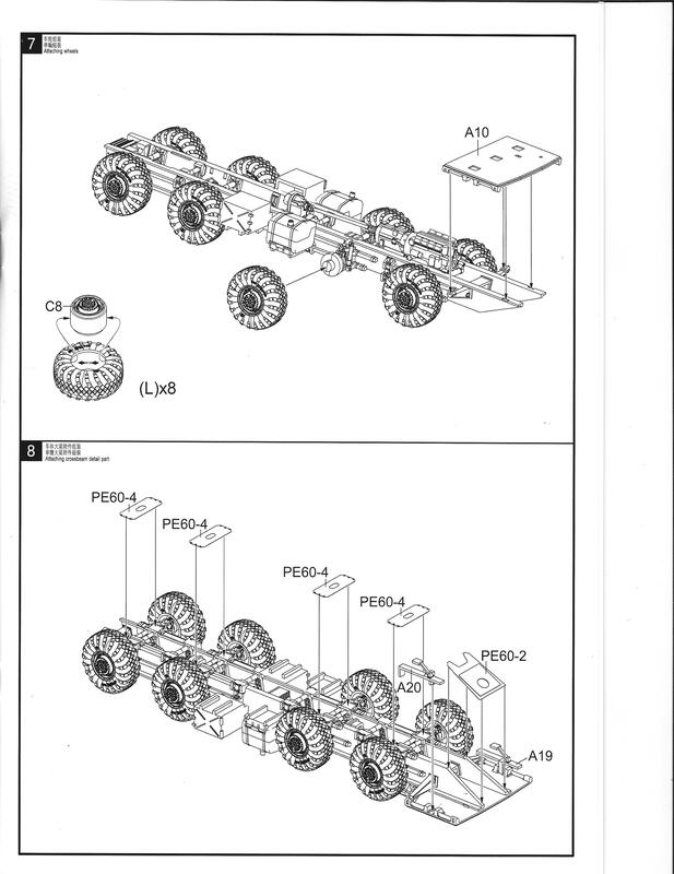
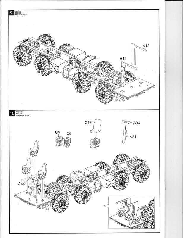
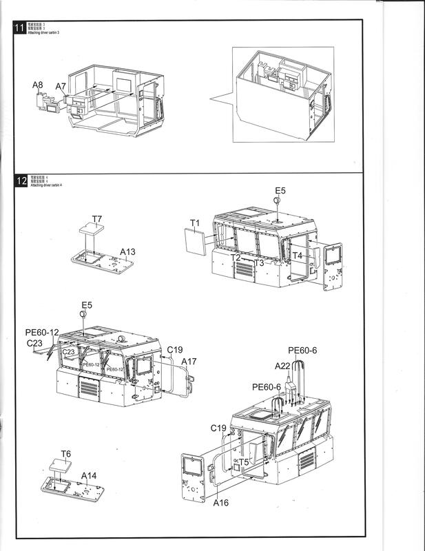
Step 7 [Iscan006] would have you install the tires and cab floor. I cleaned up the parts but will wait until later to paint and assemble them. Add the PE skid plates to the frame in Step 8 and the braces to the cab floor (which we left off) [11]. Steps 9, 10, & 11 [Iscan007,8] build out the cab interior which I will not use. The instructions are straightforward if you choose to do it. I will skip on to Step 12 but first a word about painting.
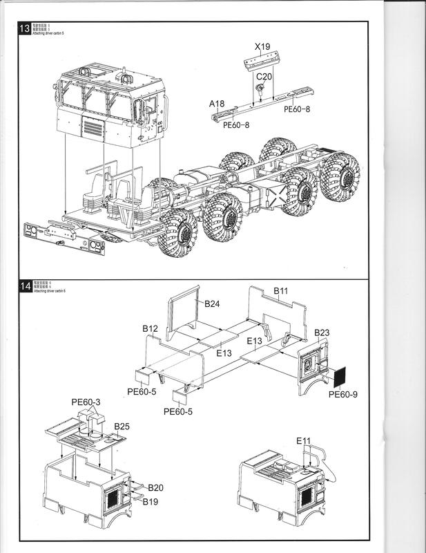
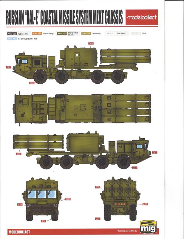
You can see in the vehicle photos that the chassis is flat black and the body is green. The painting guide [Iscan0015] shows an all green scheme. I suggest going with the black/green combo and black tire rims. Since the chassis is finished now except for the front bumper it would be a good time to take it to the paint shop along with the bumper from Step 13 [Iscan0009] and the wheel rims.
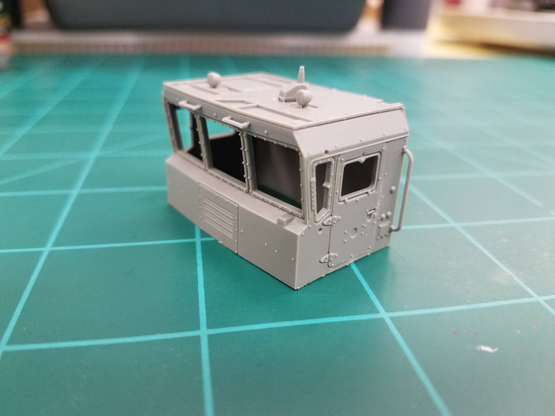
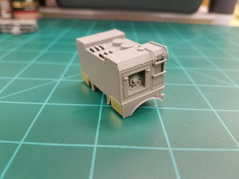
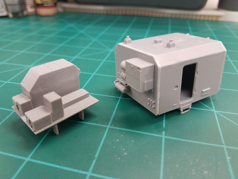
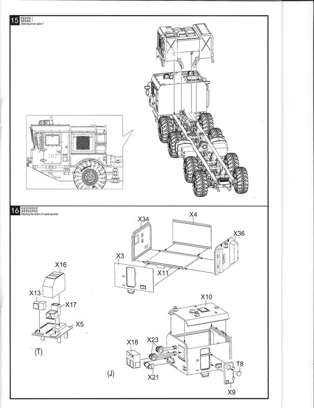
This Step 12 is essentially all the cab exterior detail and windows. I plan to build out the cab less the windows, mirrors, and wipers, then paint it and install the glass which I will paint black inside. I will finish by painting the outside of the cab floor and installing it. Here is the cab before painting [12]. Skipping to Step 14 we have the engine compartment. I have left off the PE fan shrouds and screen for separate painting so the enclosure looks like this [13]. Moving on to Step 16 [Iscan0010] we have the generator module and the missile control house. I am leaving the door off for now because I'm afraid I might pop the glass into the sealed enclosure later and that would be a big problem. Here are these assemblies [14].
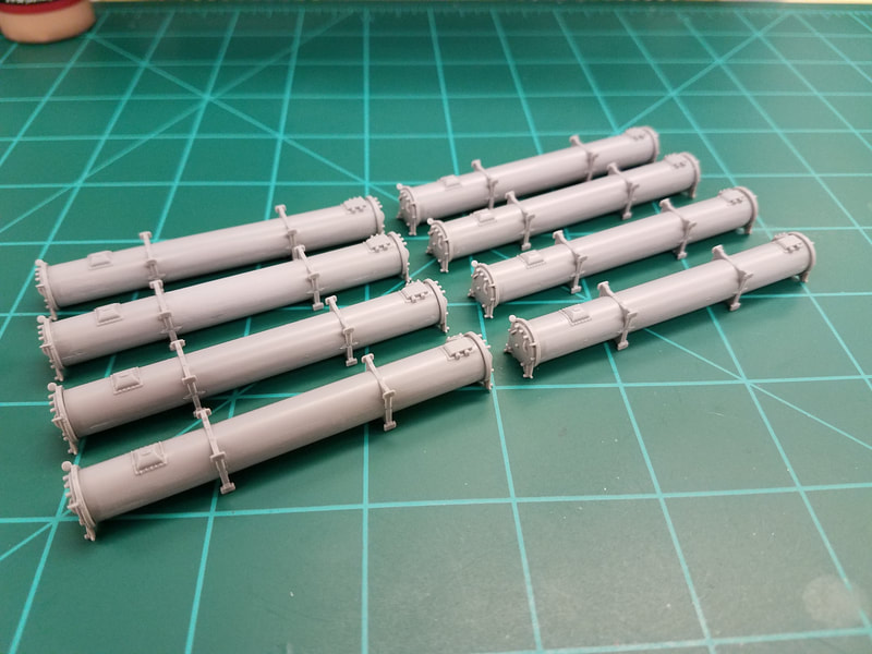
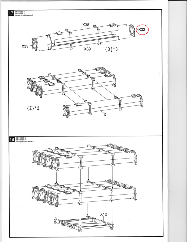
Step 17 [Iscan0011] begins with a numbering snafu: the rear tube cap is part X43 (no ears). The front cap X33 has ears. The tube seams do not fit very well but only the outer ones show the seam so pick the best ones for these locations. You will need to paint these separately before combining them or it will not get down between the tubes [15].
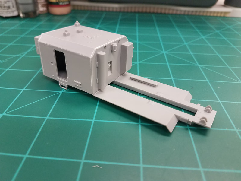
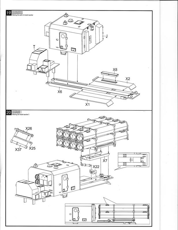
Step 19 adds the generator and control room to the body frame [Iscan0012] along with the fenders. Leave the generator module separate for now since the generator enclosure will be painted with the rest of the body. Test fit the control room to the frame first as it is used to locate the fenders. They slip just under the lip in the control room rear wall. And, yes, the hinge side of the tool box is on the outside of the fender. Don't ask me why but it is. Must be a Russian thing [16].
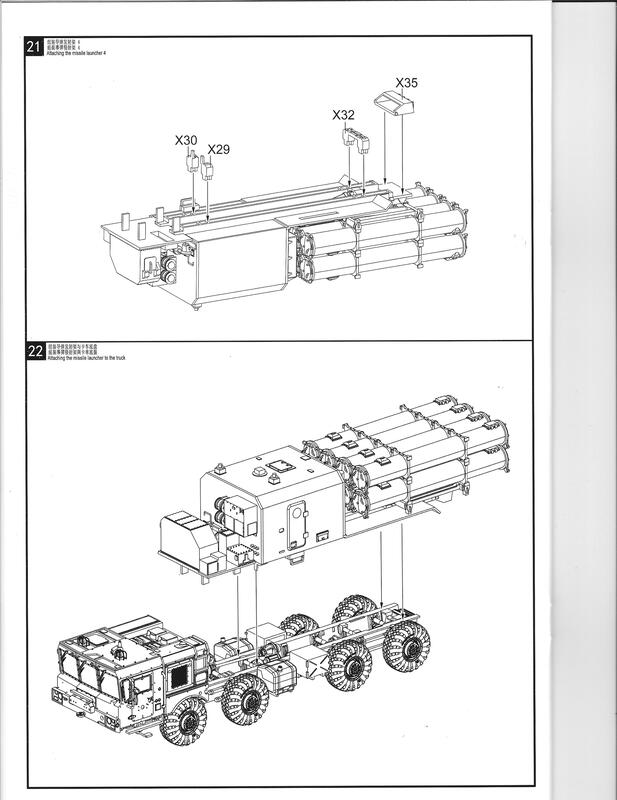
Step 20 adds the missile pack to the frame. At this point consider if you want to show the missiles in the travel mode or the firing mode. I am doing the travel mode but will not add the pack or lifts to the frame until after painting. That said, you should install the X22 piece now [17]. Confirm the location by dry fitting X7 and using the hydraulic tube to set the spacing. Notice that the cylinder attaches to X7 and the rod to X22, kinda backwards I think. Step 21 [Iscan0013] adds some under frame support pieces and completes the body construction. Now off to the paint shop with everything.
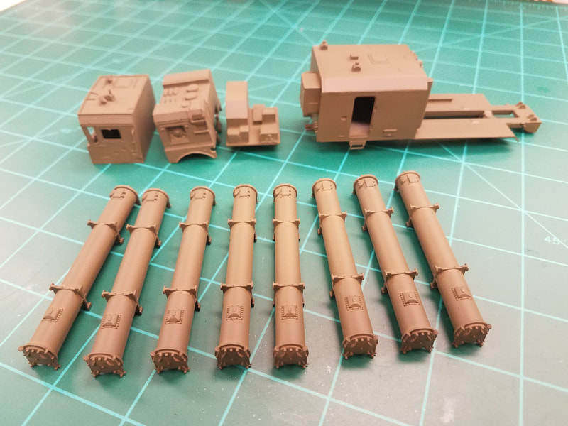
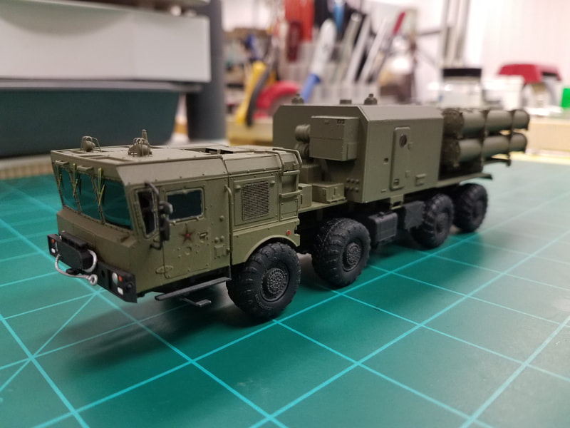
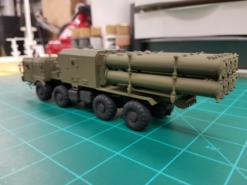
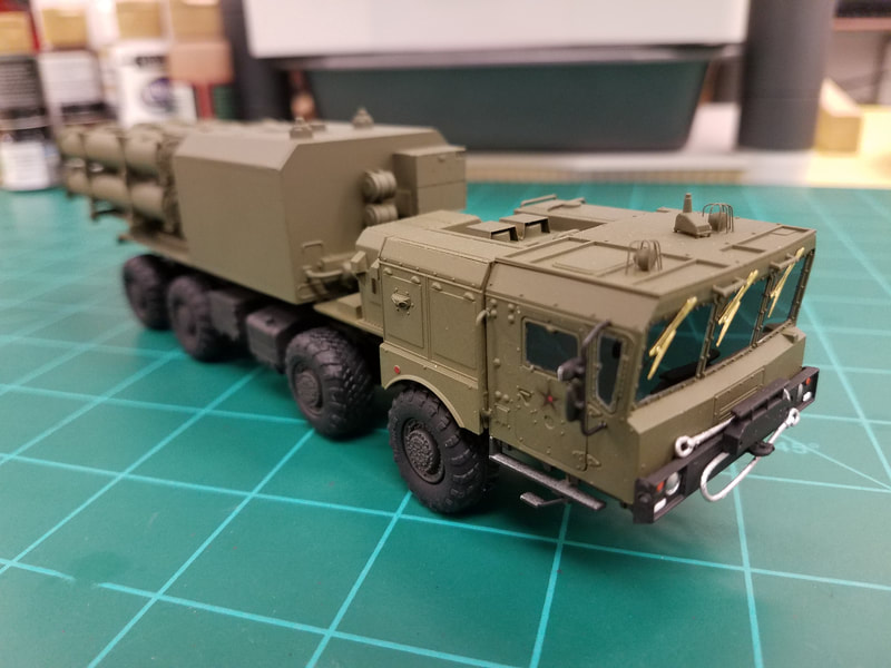
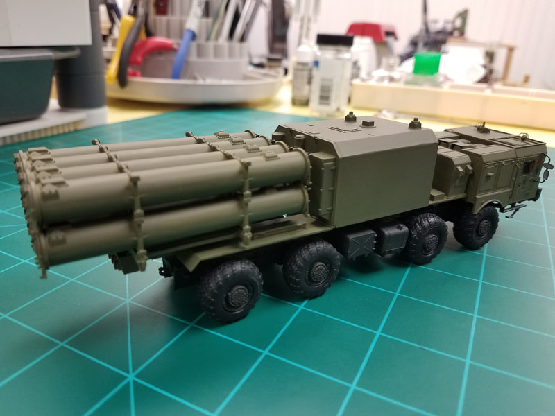
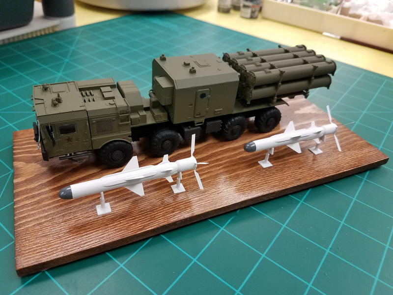
OK, here are the painted chassis and wheels [18]. The cab and engine housing, the generator and control room, and finally the missile pods [19] are ready to paint. You can see that I've also attached all those fiddly bits I left off along the way. Now its just a matter of combining it all. I suggest you start with the cab and then the engine cover. Slip the generator assembly onto the control room/pod frame (no glue) and dry fit them to the chassis to identify the glue points. Notice that the front supports for the pod frame do NOT sit on top of the chassis even though there are indents for it. The correct location is just in front of the chassis cross brace so the frame sits level. Once the frame is attached to the chassis you can combine and install the missile pods. Add the red star decals to the cab doors, a bit of touchup painting, some detail highlighting, an overspray of dullcote, and you're basically done. Here is what mine looks like:
[20,21,22,23]
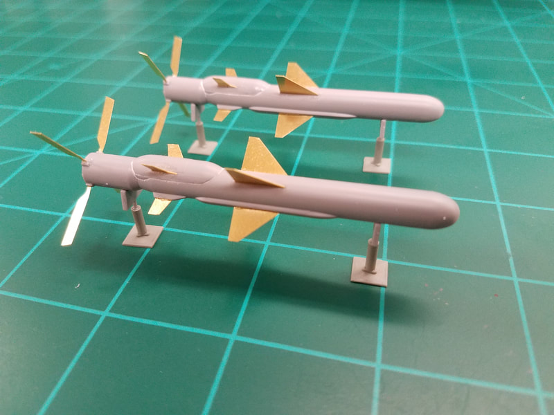
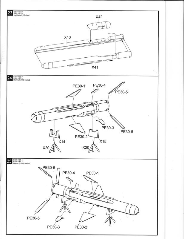
If you want to build the missiles in Steps 23,24,25 [Iscan0014] have at it. They are pretty simple but the fins are PE and a bit difficult to keep aligned, especially the rear ones and the three-legged stands are worthless. Three of the four were already broken in the box. Keep the top support parts X14/X15 but use the spare E10 pieces as the bases instead. Here are mine before [100] and after [101] painting. And in case you haven't noticed by now, there are a LOT of parts left over [xspare] to go in your spares box. Hope you have a big one!
That's it for this build. Again, questions or comments are welcome.
