Build Log of the
Takom KRAZ-6446 tractor w/ChMZAP 5247G trailer in 1/35 scale
PART: 1
By: Richard Geraci
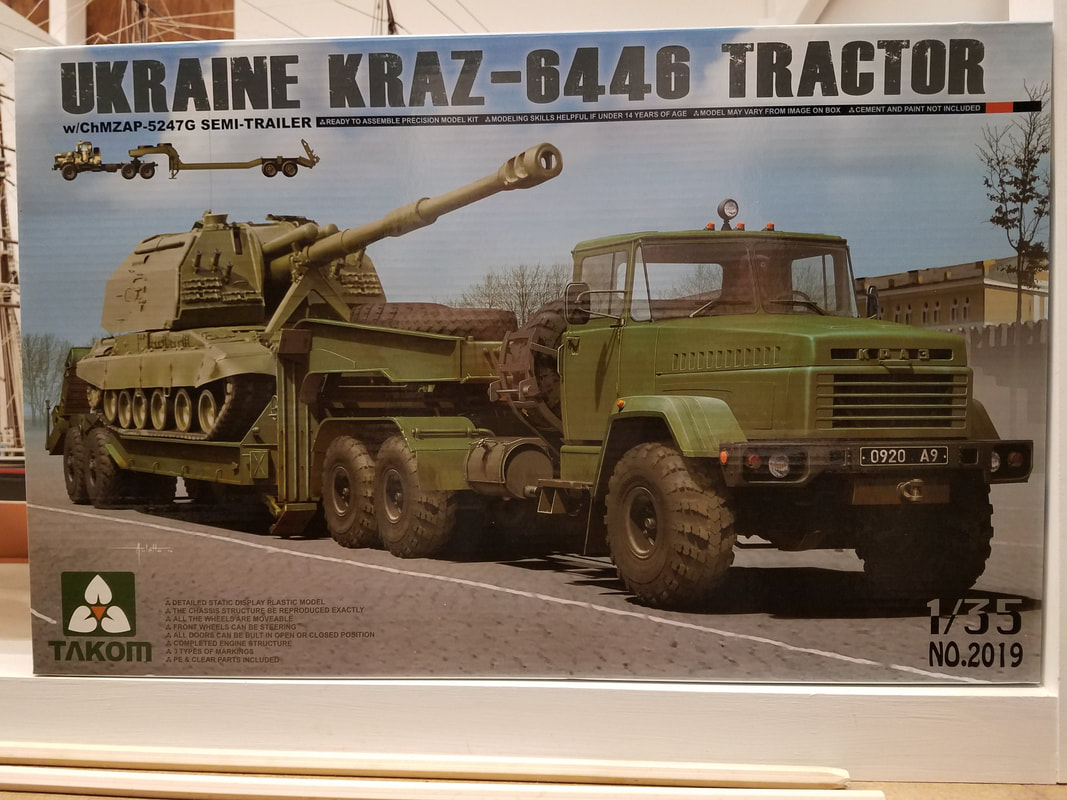
This is a kit from 2013 of the Russian KRAZ tractor & trailer 1/35 scale. At that time it was the largest kit Takom had marketed. In fact, it is actually two kits in one box [p1] It is molded in sand colored styrene with vinyl tires, two PE frets, clear parts, decals, and a short length of brass wire. Overall completed size is 4.75”W x 26.75”L so it will take up some shelf space. There are several in-box reviews and photos of the parts online so I'll not repeat them here to save space for the build itself. My load will be a T-62 Mod. 1962 from Trumpeter which will be done as a separate build.
The instructions contain a total of 82 steps along with a lot of small PE details. The wheels are all movable as are the trailer loading ramps and support legs. With come careful thought and assembly the hood and front fenders of the tractor can be made removable to show a very detailed engine. I plan to do this. Before we get started on the trailer, a word about the PE sheets – three words actually. They are very thick, the brass is really hard, and the attachment points are really big. Your creative language skills will get a workout before you are done. Nuff said.
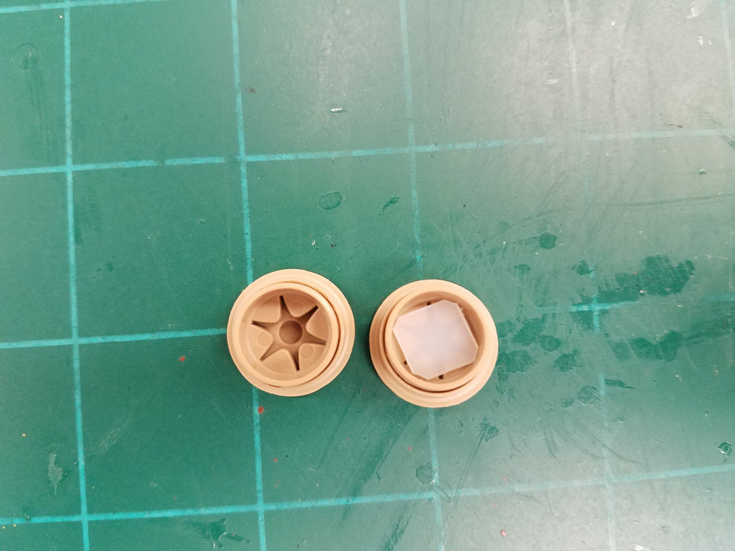
I usually start with the wheels (Step 26) just because that gives me a feel for the plastic and the general fit of the pieces. Sure enough, a couple issues right off the bat. The wheel centers D22 have tiny holes that are too small for the hub cap G55 locator pins. Either shave off the pins or enlarge the holes slightly. The instructions would have you pin the rear half of the wheel hub to the axel and later come along and glue the front half to it through the tire. This will be hard to do because the halves do not fit together all that well and also have a locator tab to deal with. Secondly, the front half of the hub is too deep and lets the pin slide too far inside if you build the entire hub first [p2]. The solution I found was to place a 1.5mm spacer in the front hub half to keep the pin extended out the back properly [p3]. This leaves just a bit of wiggle room or simply glue the pin in place if you don't want movable wheels. Here are the assembled trailer hubs [p4].
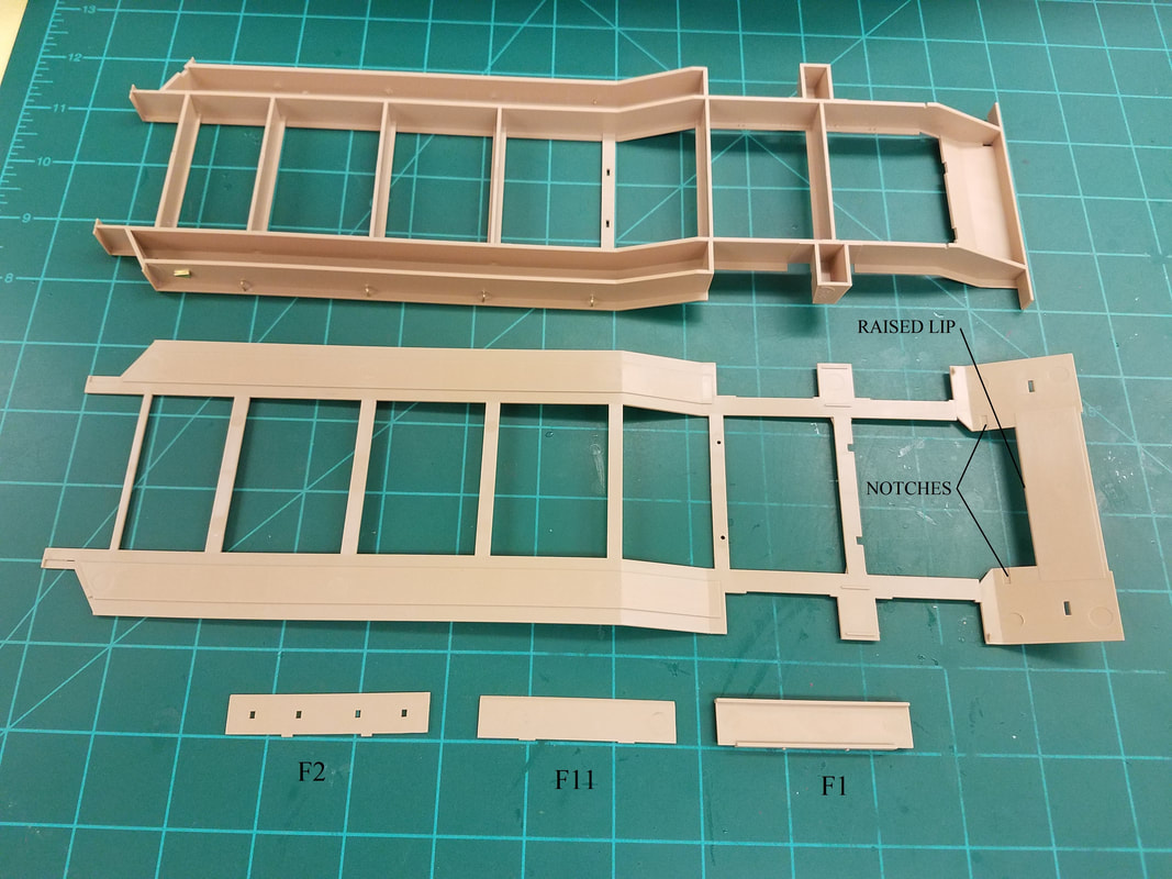
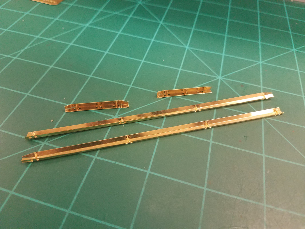
Step 1 Here we install 4 pieces of brass wire, a PE detail, and three structural lateral braces [p5]. You will need the main deck piece for reference because they do not indicate the correct angle for parts F1 and F11. There are also large ejector pin marks on these pieces but just turn them to the inside to hide them. Glue F11 to the frame, set the main deck on top, and align the part with the raised lip until the glue sets. Now glue F1 to the underside of the main deck, not the frame, using the notches for positioning. Set the deck on the frame and adjust the angle if necessary to align with the frame bottom [p6].
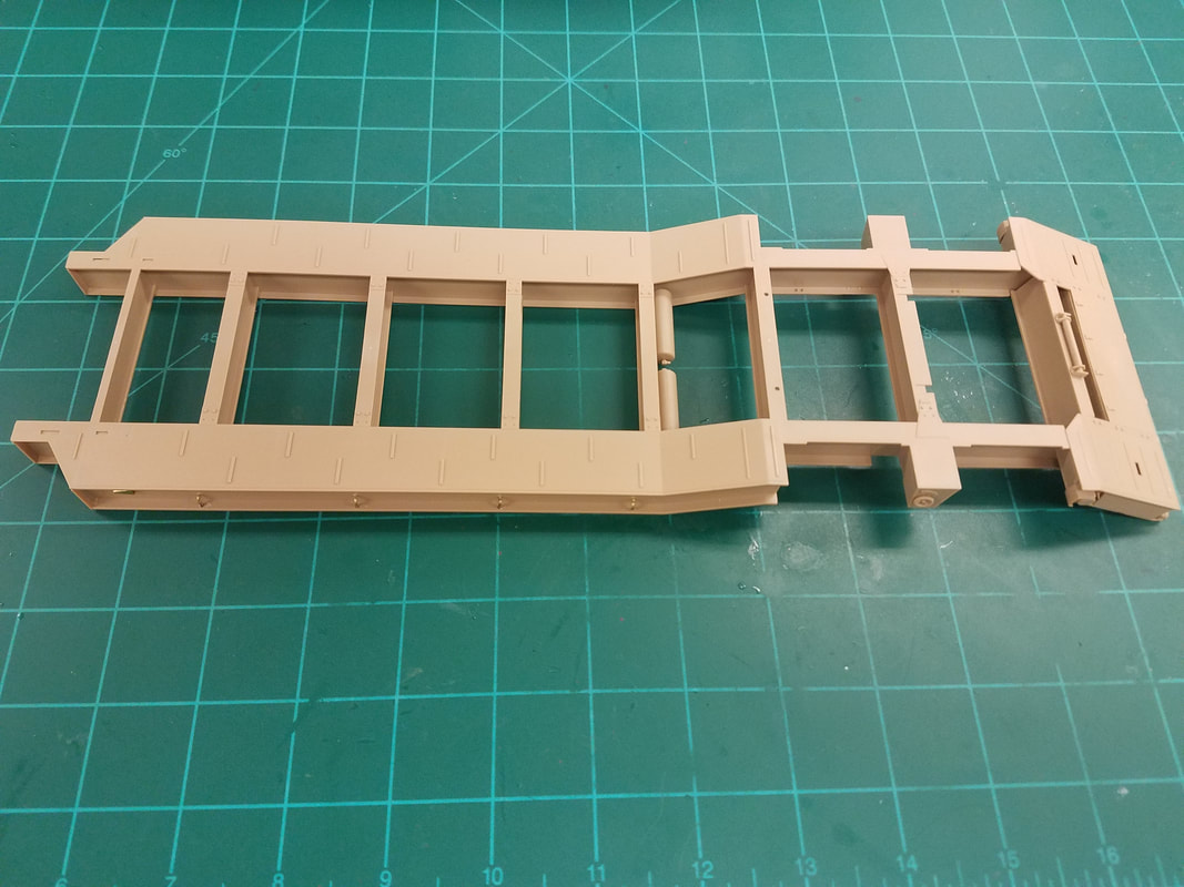
Steps 2-6 Now we add the left/right side rear enclosures, air tanks, some small details, and the rear bumper. Glue H30 to H27, let the glue grab, then glue H30 to H25 leaving H27 loose. Now fit this assembly to the frame and glue in place. Same for the other side. Glue parts G8 last after everything else is installed [p7].
Step 7 Here we attach the main deck to the frame. These are two big pieces and both of mine were slightly warped. I suggest setting the frame on a flat surface, glue a short length of the deck down, and place some weights on the whole assembly to keep it flat for a couple minutes. Then glue another length and repeat. Once it is all glued, leave the weights on it overnight to be sure everything hardens and the frame is flat [p8].
Step 8 This step is all about making the PE guide rails but there is a big SNAFU on the PE sheet. The two long rails TPa1 and TPa2 are correct mirror images of each other but the two parts Tpa13 for the short rails are identical left sides and can't be reverse bent. Sooooo, two options: 1) Leave the short rails off completely or, 2) make two left sides as shown, shave off the bolt heads on the right side deck that locate the rail, and install the left side piece reversed on the right. The gussets will not exactly line up on both sides and the entry/exit angles of the rails will be a bit different but nobody will likely notice that. I made two left sides and will reverse one for the right. Here's how that turned out [p9]. They ain't pretty but they're done and you won't see them under the loading ramps and tank anyway.
Step 9 Here we install the rails from Step 8 and get to make some more (Oh Goodie!). Leave parts G17 off for a few more steps to assure a good connection to the goose neck frame when it is installed later [p10].
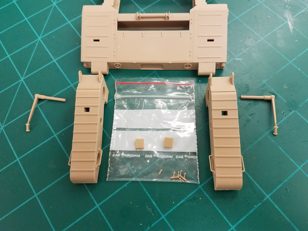
Steps 10-15 These steps cover the assembly of the loading ramps which can be made movable if you so choose. Leave parts G38,39, 45 off until after painting and decals. Glue the handles to the shafts but leave them off as well. Glue H40 & H43 to the chassis, flat side goes down. The ramps can easily be attached later [p11].
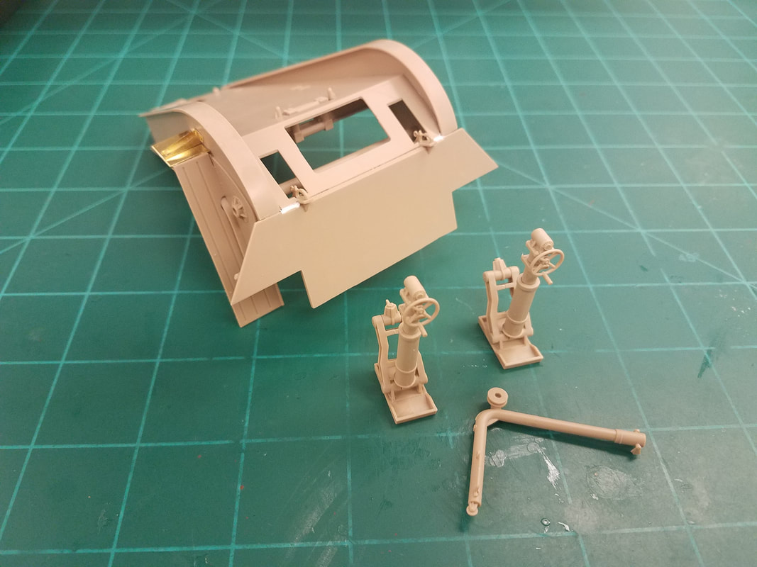
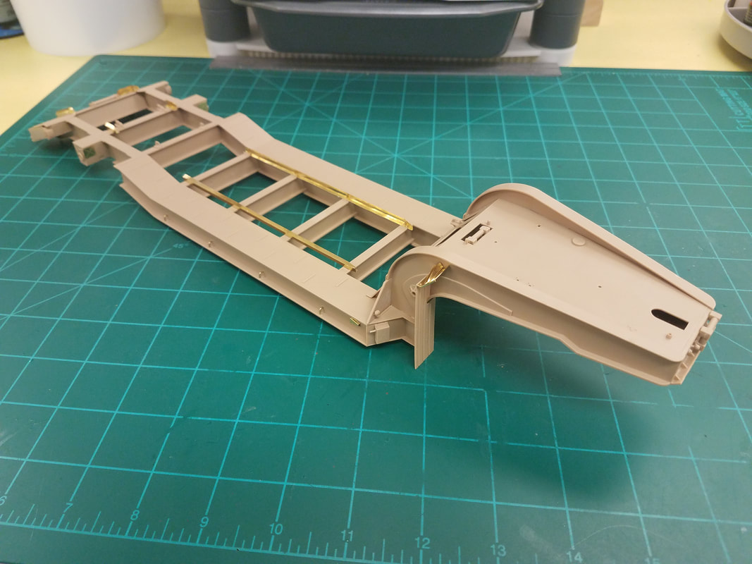
Step 16-23 Now for the goose neck. Nothing difficult here, just a lot of little pieces and some PE work again. Here is the end result [p12].
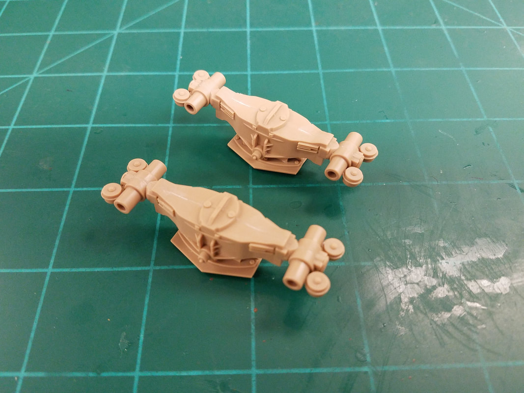
Steps 24-30 Build the transaxles as indicated but don't put the wheels on yet. Note that part G12 is not symmetrical and the wider flange side is oriented toward the axle part with the pin H12. Also, the brake cylinders should be reversed – G31 on the left, G32 on the right – at least to me. Same for the other pair. Otherwise you have a big hole exposed rather than a flat surface with a bolt head. You decide [p13]. Can't see them anyway behind the wheels.
Steps 31, 34 Now add the goose neck, frame support legs, and a couple details. Leave the transaxles and legs off for separate painting [p14].
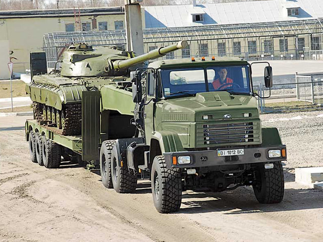
OK, off to the paint shop with the chassis and all the pieces we left off. There are lots of photos on the internet that show the trailer in color. Take your pick but it is usually just solid, no camo. Here is the one I am using as a go-by [p15]. I'll use Krylon satin Italian Olive from a rattle can which is glossy enough that the decals won't silver without the intermediate step of a gloss coat [p16].
Now with everything painted I'll go back and install all the stuff I left off earlier, add a few decals, touch up the paint, and hit it with a light overall spray of Dullcote. The decals must be trimmed to fit the loading ramps and needed several applications of Solvaset to lay down. Here is the finished trailer [p17-p20].
In Part 2 I'll build the KRAZ tractor.
The instructions contain a total of 82 steps along with a lot of small PE details. The wheels are all movable as are the trailer loading ramps and support legs. With come careful thought and assembly the hood and front fenders of the tractor can be made removable to show a very detailed engine. I plan to do this. Before we get started on the trailer, a word about the PE sheets – three words actually. They are very thick, the brass is really hard, and the attachment points are really big. Your creative language skills will get a workout before you are done. Nuff said.
I usually start with the wheels (Step 26) just because that gives me a feel for the plastic and the general fit of the pieces. Sure enough, a couple issues right off the bat. The wheel centers D22 have tiny holes that are too small for the hub cap G55 locator pins. Either shave off the pins or enlarge the holes slightly. The instructions would have you pin the rear half of the wheel hub to the axel and later come along and glue the front half to it through the tire. This will be hard to do because the halves do not fit together all that well and also have a locator tab to deal with. Secondly, the front half of the hub is too deep and lets the pin slide too far inside if you build the entire hub first [p2]. The solution I found was to place a 1.5mm spacer in the front hub half to keep the pin extended out the back properly [p3]. This leaves just a bit of wiggle room or simply glue the pin in place if you don't want movable wheels. Here are the assembled trailer hubs [p4].
Step 1 Here we install 4 pieces of brass wire, a PE detail, and three structural lateral braces [p5]. You will need the main deck piece for reference because they do not indicate the correct angle for parts F1 and F11. There are also large ejector pin marks on these pieces but just turn them to the inside to hide them. Glue F11 to the frame, set the main deck on top, and align the part with the raised lip until the glue sets. Now glue F1 to the underside of the main deck, not the frame, using the notches for positioning. Set the deck on the frame and adjust the angle if necessary to align with the frame bottom [p6].
Steps 2-6 Now we add the left/right side rear enclosures, air tanks, some small details, and the rear bumper. Glue H30 to H27, let the glue grab, then glue H30 to H25 leaving H27 loose. Now fit this assembly to the frame and glue in place. Same for the other side. Glue parts G8 last after everything else is installed [p7].
Step 7 Here we attach the main deck to the frame. These are two big pieces and both of mine were slightly warped. I suggest setting the frame on a flat surface, glue a short length of the deck down, and place some weights on the whole assembly to keep it flat for a couple minutes. Then glue another length and repeat. Once it is all glued, leave the weights on it overnight to be sure everything hardens and the frame is flat [p8].
Step 8 This step is all about making the PE guide rails but there is a big SNAFU on the PE sheet. The two long rails TPa1 and TPa2 are correct mirror images of each other but the two parts Tpa13 for the short rails are identical left sides and can't be reverse bent. Sooooo, two options: 1) Leave the short rails off completely or, 2) make two left sides as shown, shave off the bolt heads on the right side deck that locate the rail, and install the left side piece reversed on the right. The gussets will not exactly line up on both sides and the entry/exit angles of the rails will be a bit different but nobody will likely notice that. I made two left sides and will reverse one for the right. Here's how that turned out [p9]. They ain't pretty but they're done and you won't see them under the loading ramps and tank anyway.
Step 9 Here we install the rails from Step 8 and get to make some more (Oh Goodie!). Leave parts G17 off for a few more steps to assure a good connection to the goose neck frame when it is installed later [p10].
Steps 10-15 These steps cover the assembly of the loading ramps which can be made movable if you so choose. Leave parts G38,39, 45 off until after painting and decals. Glue the handles to the shafts but leave them off as well. Glue H40 & H43 to the chassis, flat side goes down. The ramps can easily be attached later [p11].
Step 16-23 Now for the goose neck. Nothing difficult here, just a lot of little pieces and some PE work again. Here is the end result [p12].
Steps 24-30 Build the transaxles as indicated but don't put the wheels on yet. Note that part G12 is not symmetrical and the wider flange side is oriented toward the axle part with the pin H12. Also, the brake cylinders should be reversed – G31 on the left, G32 on the right – at least to me. Same for the other pair. Otherwise you have a big hole exposed rather than a flat surface with a bolt head. You decide [p13]. Can't see them anyway behind the wheels.
Steps 31, 34 Now add the goose neck, frame support legs, and a couple details. Leave the transaxles and legs off for separate painting [p14].
OK, off to the paint shop with the chassis and all the pieces we left off. There are lots of photos on the internet that show the trailer in color. Take your pick but it is usually just solid, no camo. Here is the one I am using as a go-by [p15]. I'll use Krylon satin Italian Olive from a rattle can which is glossy enough that the decals won't silver without the intermediate step of a gloss coat [p16].
Now with everything painted I'll go back and install all the stuff I left off earlier, add a few decals, touch up the paint, and hit it with a light overall spray of Dullcote. The decals must be trimmed to fit the loading ramps and needed several applications of Solvaset to lay down. Here is the finished trailer [p17-p20].
In Part 2 I'll build the KRAZ tractor.