Build Log of the
Takom KRAZ-6446 tractor w/ChMZAP 5247G trailer in 1/35 scale PART 2
By: Richard Geraci
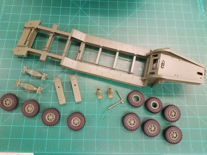
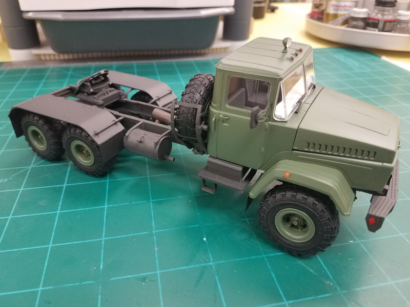
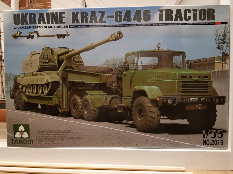
This is the tractor build part of a kit from 2013 of the Russian KRAZ tractor & trailer 1/35 scale [p1]. My load will be a T-62 Mod. 1962 from Trumpeter which will be done as a separate build.
The wheels are movable and with some careful thought and assembly the hood and front fenders can be made removable to show a very detailed engine. I plan to do this. Before we get started on the tractor, a word again about the PE sheets – three words actually. They are very thick, the brass is really hard, and the attachment points are really big. Your creative language skills will get a workout before you are done. Nuff said. Unlike the trailer build, I'll do some painting as I go along because it will be hard or impossible to do later on. Note that the frame and chassis are a dark charcoal color while the fenders, tire rack, and cab are green [p16].
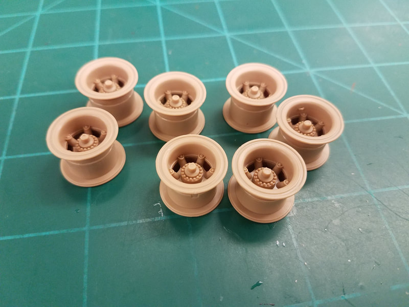
I started again with the wheels in Step 81. And just like the trailer hubs there is a problem right off. Part A3 is slightly too large to fit into A2 and the locator tab is a tad too long. You have to trim the inside edge of A2 a good bit to get them to mate properly. You won't see the trimmed edge so get hacking. Here are the assembled tractor hubs [p20].
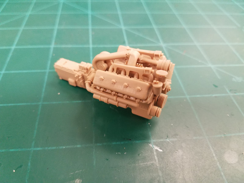
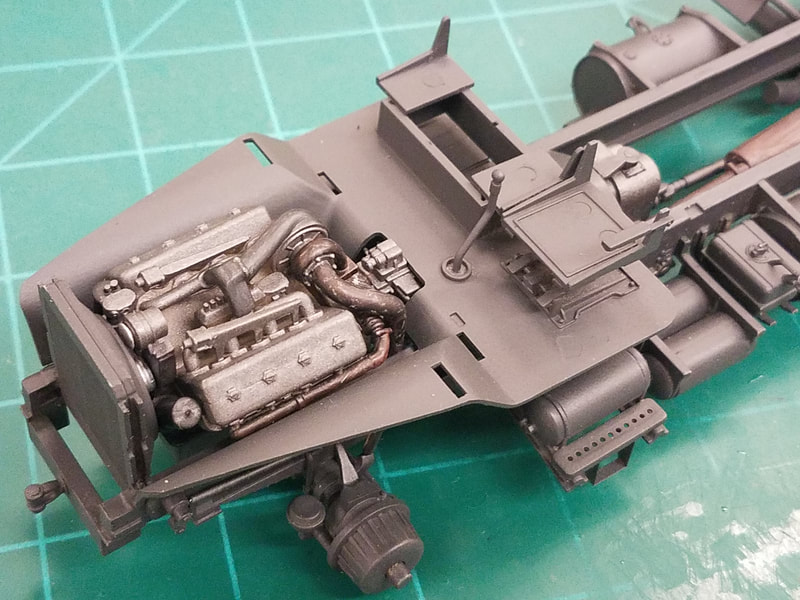
Step 35-42 Construction begins with the engine. The fit here is pretty good considering all the pieces involved. I have left off the fan blade and exhaust pipe/muffler for now [p21]. At this point I'll paint/detail the engine and exhaust [p22].
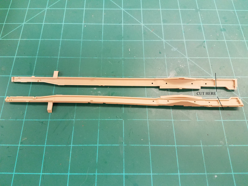
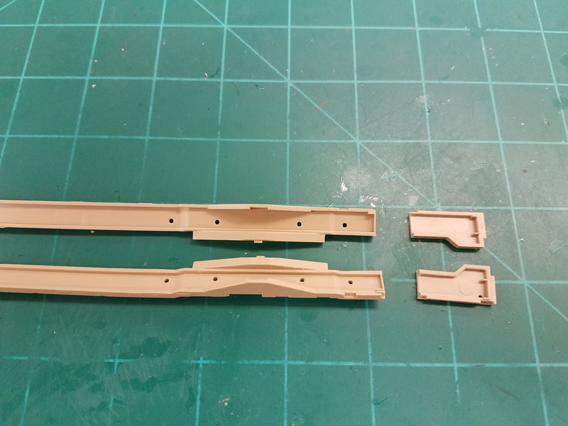
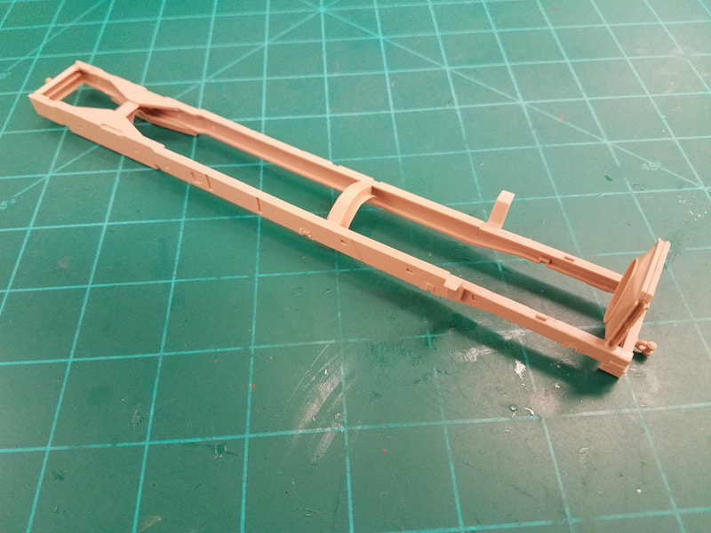
Step 43 This chassis frame is also used for a different version of the KRAZ so they have you amputate a portion at the rear to shorten it. The cut occurs at a gusset which helps. Here are before [p23] and after [p24] pics. The engine (now painted) and exhaust pipe do not have to go in at this point as they can drop in later. The supports A25 should not be installed now to allow this. A bit of creative masking will still be needed when painting the chassis later. My frame rails had both a twist and a warp so I built assembly “C” from step 49 and installed it after gluing the radiator in place to square up the front. Then I added parts C40 and B41 (from step 50) to straighten the rest of the frame. Finally, I added assembly “K” from step 59 (amputation again required) to close up the rear of the frame. It's not perfect but a lot better [p25].
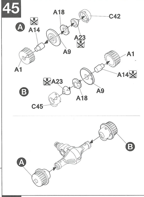
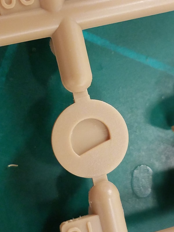
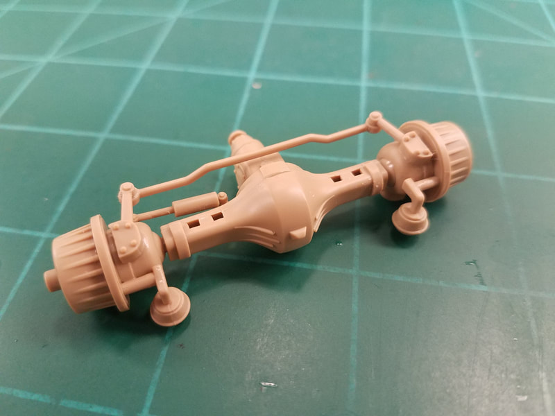
Steps 44, 46 Here we build the front transaxle and there is a major issue in step 45 [p26], actually several of them. First there is a VERY small locator tab on the side of part A18 [p27] that is easily trimmed away when you cut it from the sprue. It orients part C42/45. I missed it on one but fortunately caught it on the other one. Second, if you align and glue the shallow 'D' tab on A18 to A9, part C42/45 is about .5mm too deep to capture A23 properly and it just flops around. If you slip A18 into C42/45 to capture A23 then you can't align and glue it to A9 because it is .5mm too far away. The only reason A23 is movable at all is to set a steering angle for the front wheels in step 46. They are not actually steerable. If you sand down the .5mm on C42/45 to make it all fit, the tie rod B51 will be 1mm too long and not fit. What to do?? I decided to slip A23 into C42/45, use A18 to align it, glue it in place from the front, and then remove A18. I then glued A18 to A9, and lastly C42/45 to A9. The wheels will be fixed straight ahead, which is fine with me, and the tie rod will now fit [p28]. Big PITA.
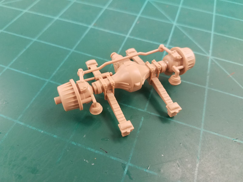
Steps 47-48 Add the leaf springs to complete the front transaxle. The springs do not have very good alignment tabs so use the chassis to keep them straight while the glue sets. Now add the shackles [p29].
Steps 49-51 We have already done part of this assembly. Build the transmission box, clean up the steering parts but don't glue the transmission or front axle in the frame yet.
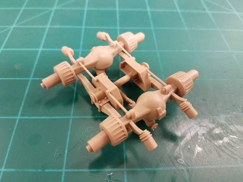
Steps 51-57 Next we build the rear transaxles/differentials. Nothing surprising here, just use the frame as a jig to keep everything straight and aligned as you go along [p30]. Skip step 58 &59 for now.
Steps 60, 61 This is the tire rack, equipment cabinet, air and fuel tanks. I glued the cabinet together first, added the tire rack sides to it and then fitted the PE rungs in between. Still not an easy thing to do as they are mucho flimsy. Also, there is a parts SNAFU here. The air tank ends A16/A17 are for Step 64 and vice-versa. Toss part A22. It goes through the spare hub to secure it and will be totally hidden even if you could get it installed. Remember, patience is a virtue.
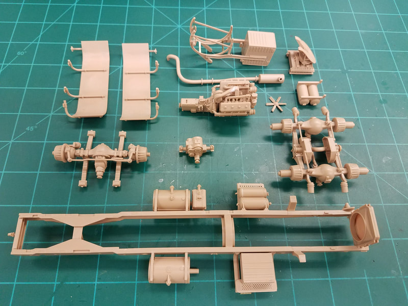
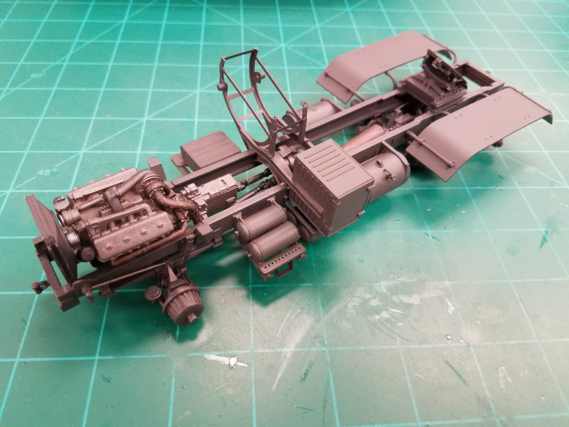
Steps 62-66 You need to make a decision here. These steps have you build the remaining items that mount to the frame including the previous ones as well as the fenders. Adding these will complicate painting and installation of the motor and transaxles but it's up to you how to proceed. For me, I'll build the sub-assemblies, install some of them, paint some of them separately along with the frame, and then go back to step 43 to install the motor and exhaust. I'm doing this because some of the parts do not fit well to the frame and will be a mess to add after painting. It means more touch up but I think it will look OK. Here are the parts before painting [p31].
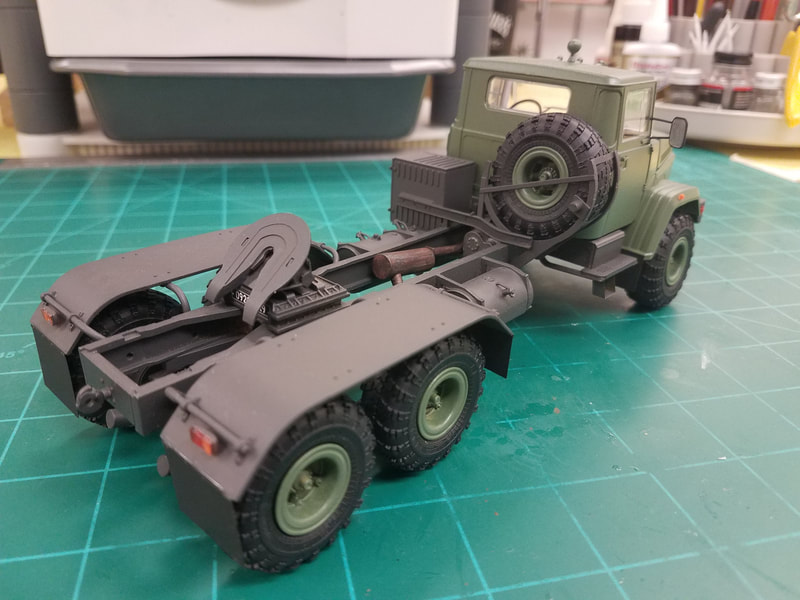
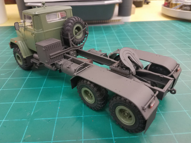
To install the motor, drop it into the frame from the top, flip the frame over, and let the oil pan extend as far out of the frame bottom as possible. Glue the A25 support pins into the oil pan and let them set up. Then gently lower the motor down into the frame letting the A25 pins slide into the locating slots. Add the front transaxle, steering parts, and transmission box. Add the rear transaxle and miscellaneous drive parts . Touch up paint if needed. Now add all the rest of the frame mounted items and touch up paint again if needed, including a final spray of Dullcote. The only decals are license plates if you want them [p32].
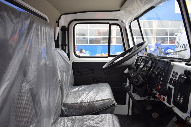
Step 67-75 This begins the cab assembly. Fortunately, the windows insert from the outside so masking won't be an issue. From the photo I've found the interior appears to be beige, less the insulation, with a black floor, gray seats, and black/white dashboard and doors [p33]. The only real detail inside is the driver's seat support, which you will NEVER see again. I'll pre-paint the cab wall/ceiling/door parts inside, assemble them, and then mask off the openings on the inside. Next I'll paint the inside floor less the seats and install it on the chassis [p34]. Next I'll paint the exterior. Once dry, remove the masking and all the pieces can be put together, including the windows, and placed on the chassis.
Steps 76-80 Here you build the hood and fenders. As I mentioned before, you can make this assembly removable if you dry fit the parts first and slightly enlarge any points that touch too tightly. Paint and add the decals and mud flaps.
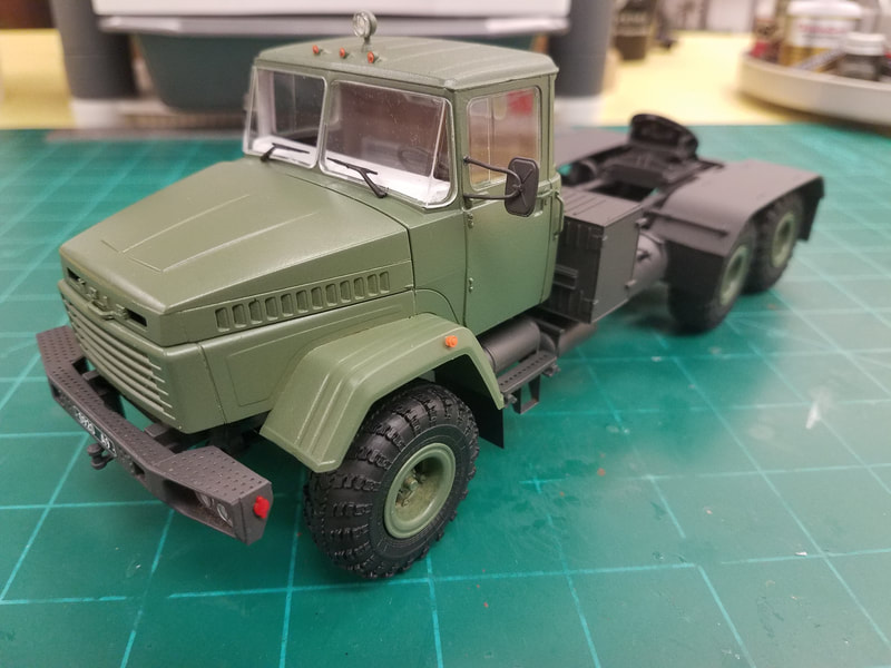
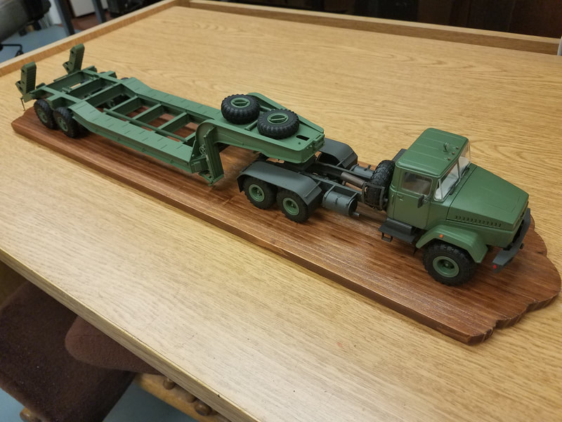
Steps 81-82 Just install the tires and were done [p35-38]. Here are the tractor and trailer together on a wood base [p39] waiting for the T62 load.
There were a lot of little fit issues along the way that I did not mention but any modeler with a little experience will know how to handle them. Now on to the T-62.
