Dragon has produced some armor kits that are beautiful and highly detailed. Dragon has also turned out others that fall into the “not so much” category when it comes to quality. Their Orange Box “Sherman M4A4 75 mm” is one of the latter.
The M4A4 Sherman tank had a powerplant consisting of five six-cylinder Chrysler automobile engines arranged in radial fashion around a common drive shaft. The M4A4’s hull had to be lengthened to accommodate this setup. One sure way to identify one of these tanks is the extra space between its suspension units. Another unique M4A4 feature: humps on the engine deck and hull bottom that were needed to make room for a massive common radiator for the five Chrysler engines.
Most M4A4s were used by allies of the U.S. in World War II. The British employed many of them as mounts for their excellent 17-Pounder antitank gun. The Chinese also received this Sherman model and some of the M4A4s serving with the 1st Provisional Tank Group in Burma were crewed by Americans. Dragon’s Kit No. 9102 purports to represent one of these. And there’s the rub—the kit can be made to replicate a short-gun M4A4 in the India-China-Burma theater, but only if the builder combines a disregard of substantial parts of the kit instructions with some research.
What Dragon did with this kit was to take sprues from a Firefly model (the British name for their M4A4 with 17-Pounder gun), throw in a few other sprues, and call it an “American in Burma.” The first page of the kit instructions reveals that a large number of parts supposedly will not be used. More on that later in the article. The thrown-together nature of this kit is also revealed by the inclusion of a bonus set of crew figures—a U.S. tank crew in Northwest Europe, 1944. U.S. forces in Europe did not use M4A4s.
What would any kit build be without challenges, though? This one provides plenty of those! Starting from the bottom up, the first thing to be rectified is “DS” tracks that are well-detailed but too long—aggravating, but easy to fix. Cut two links off each track run, grind out the receiving end of the track as well as can be with a small ball cutter, glue and clamp. The tab on the “male” end of the track is plenty long, and the bumps on the two removed links designed to help hold things together are pretty puny anyway. If the springy DS tracks are used, they will have to be glued down to the return rollers even after shortening the track. A proper-length track will nevertheless be a vast improvement.
The kit’s tracks are of the rubber chevron variety. Chinese M4A4s in surviving photos appear to have steel chevron tracks; the track type on the American Shermans couldn’t be determined by this author. One thing that is certain, however, is that tracks of all types were found on Shermans in the Pacific, and with Burma being one of the stepchildren of the war when it came to supplies and equipment, rubber chevron tracks are as likely as any other type.
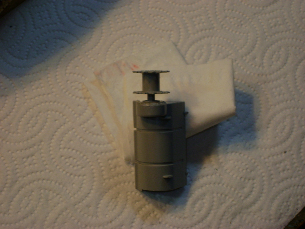
The VVSS (Vertical Volute Spring Suspension) units are nicely detailed and designed to articulate. Trapping the springs inside the units is a bit tricky, but only on the first try. A very bizarre situation comes to light with the drive sprockets, however. Used as given, the sprockets will stand way too far out from the hull sides. The fix for this is to cut the sprocket shafts and the parts that will receive them (Parts C8 & 9) down by about an eighth of an inch each. Getting out the old power drill would work, too, as long as the drilling doesn’t go too far; the edges of the transmission cover block the drive sprocket shafts from seating fully in Parts C8 and 9. Which is mighty odd.
Care is needed when attaching the transmission cover/drive sprocket assembly to the forward part of the lower hull. If the front of the upper hull won’t fit, this assembly is not installed correctly. This modeler, after prying these pieces apart to fix an improper joining, used styrene strips inside the lower hull to strengthen the very inadequate method Dragon used to mate these pieces. Still haven’t figured out the strange gaps where Parts H11 and H12 meet Part C1. Take care with placement of C1, the strip of bolts that represents where the transmission cover joins with the upper hull. Much finagling may be needed to figure out which end is up with this piece; the instruction drawings are not very helpful with that.
The back end of the upper hull fits very loosely onto the lower hull, and only a very narrow ledge is provided for this purpose. Wide pieces of styrene glued onto the inner sides of the upper hull, level with this ledge, will allow the upper hull to sit properly and securely.
Moving upward, the next difficulty involves the strips around the bottom of the upper hull sides and part of the upper hull rear that sand shields would be bolted to. These shields were never seen on Shermans that operated anywhere mud might commonly be found—places like Europe and Burma. Since the shields aren’t mounted, they should display empty bolt holes, but for some strange reason, Dragon molded them with bolt heads. Shaving off the bolt heads is easy; drilling holes in their places and getting the holes in a straight line—not so easy—but it must be done. There is also a pesky seam that runs through the center of these strips along the entire length of the hull sides.
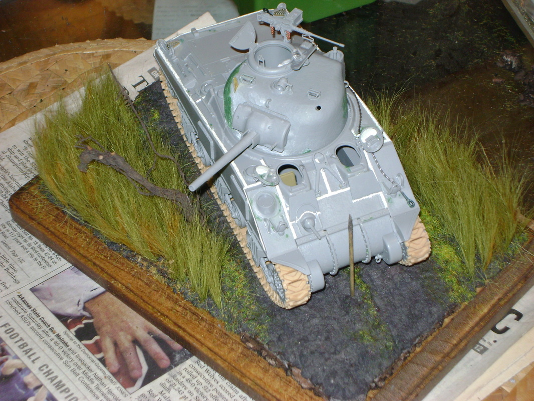
Next up, the rear of the upper hull needs a bit of work. Brackets that would hold the long stowage box carried by most British Shermans need to go. No huge deal there. The M4A4s used in Burma should carry the track-tensioning tool, a few small bolts, and nothing else on the rear of the upper hull.
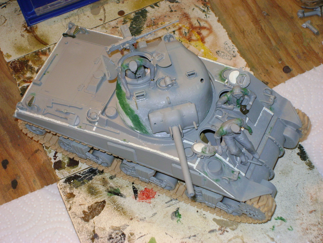
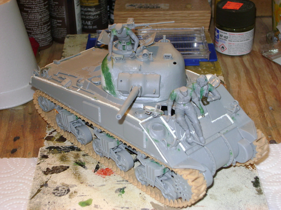
For some reason, it’s common for models of the Sherman to be molded with recessed weld seams on their hulls. This kit is no exception. This can be corrected with styrene rod softened with liquid cement and then textured, or with thin ropes of epoxy putty similarly textured. This modeler used the latter method to replicate proper raised weld beads. Beads of liquid cement replicated welds around splash guards and in a couple of other areas.
The hatches for the driver and assistant driver/bow gunner are not intended to be modeled open. Surgery is needed to correct this. The molded-in rotating mounts for periscopes must be drilled and carved out. Once that’s done, the “not-to-be-used” parts provide replacements for those mounts, as well as periscopes, periscope covers, and brush guards. The instructions show no installation of the wire guards that protected periscopes on Shermans from brush and other hazards, but they are included in the kit. Spares from other Sherman kits or after-market pieces will have to provide brush guards for the turret periscopes.
There is no indication in the kit instructions that this M4A4 should have a travel lock for the 75mm gun, even though research shows it should. Well, guess what? That’s right; the “not-to-be-used” parts come to the rescue again, and in full.
Photos of an American-crewed M4A4 in Burma show that it had no shell ejection port on the left side of the turret, so the molded-in detail there has to be ground away. The opening for the port is then backed with thick styrene sheet and epoxy putty fills the hole. Photos also show this tank had integral supplemental cheek armor added to the forward portion of the turret on the right-hand side. This extra armor was installed to protect a weak spot in the vehicle’s turret armor. The Dragon kit supplies a curved, welded-on plate for this area. Part of this kit piece combined with a lot of putty and much sanding will reproduce the proper cast-in supplemental armor.
The only truly strange part of turret assembly has to do with mounting the assembled 75mm cannon and mantlet. The entire thing will fall right through the opening provided for it in the turret front unless styrene strips are used as backing pieces on the inside! Weird? You bet!
The photographs of an M4A4 in Burma referred to above are of a vehicle driven by Sgt. Leonard Farely, and why Dragon didn’t use its markings for this kit is mystifying. The hull of Sgt. Farely’s “Fight or Frolic” bears different paintings of scantily-clad ladies on each side. The port side of the turret displays the triangular Armored Corps insignia, while the starboard turret side bears the profile of a human skull. The photographs of this tank are not the clearest; otherwise your author would definitely have reproduced the cheesecake art by hand. The markings for Dragon’s “Lucky Eleven”, the only decals in the kit, are pretty plain.
MiniArt produces a set of U.S. tankers in herringbone twill fatigue uniforms suitable for adapting to an Asian setting. One has sleeves rolled up; another has an unbuttoned fatigue jacket. Don’t use any of the lower torsos featuring gaiters (three of the five figures in this set do)—those leggings were despised in all theaters, and rarely if ever seen on tankers in the Pacific or Asia. MiniArt has also produced a set of Afrika Korps figures with bare torsos, and these are handy for doing figures of shirtless tankers in the hot and humid climate of Burma.
If you are an armor builder who’s tired of “shake the box” kits—kits that just fall together—try this one. If you can turn it into an acceptable replica of an American-manned fighting machine in one of the most difficult and crucial battlegrounds of World War II, that feat should give you a real feeling of accomplishment. (And yes, blunting the Japanese threat to India and tying down as many Japanese as possible in China and Burma was crucial).
Taking the kit instructions with a grain of salt and doing some hunting for references are musts for this build. A little more research by Dragon would have been nice, but maybe what they save there goes into keeping Orange Box prices low. One thing is sure: Turning what some would call a “dog” of a kit into a decent model is what separates the men from the boys in the world of glue and styrene.
